Circuit Analysis of the Orange AD15 Guitar Amplifier
"Two of the new designs of a revitalized Orange, the AD30 and AD15 of 1998 and '99 respectively, captured great Orange-meets-Vox tones in thirty and fifteen-watt renditions using EL84-based output stages and manufactured with quality PCBs and a lot of hand-wiring. Both became near overnight successes and won awards from guitar magazines on both sides of the Atlantic." 1 -Dave Hunter
Power Amp
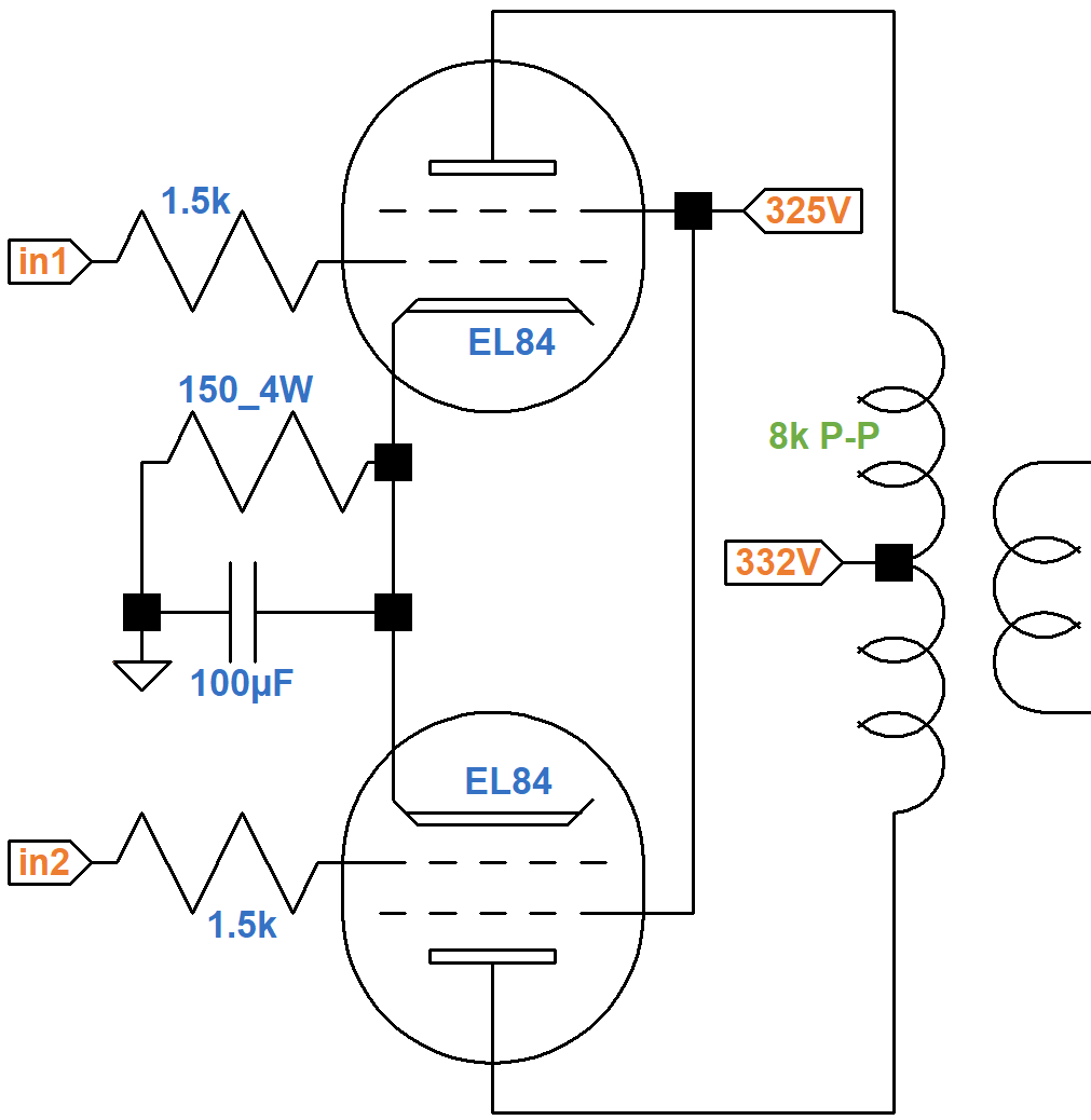
The power amp has a pair of EL84 pentodes in push-pull with cathode bias and no negative feedback.
A Sovtek EL84 data sheet includes plate and screen transfer characteristics when both the plate and screen are at 300V. Using the upper solid curve for plate current and the upper dashed curve for screen current, we see that for a -6.6V grid, the plate current is 65mA and the screen current is 5mA, as depicted by where the red line crosses the two curves.
The cathode current is their sum: 70mA. Assuming the ratio of plate current to screen current is approximately constant, the ratio of cathode current to plate current is also constant:
(70mA) / (65mA) = 1.07

|
Guitar Amplifier Electronics: Fender Deluxe - from TV front to narrow panel to brownface to blackface Reverb |
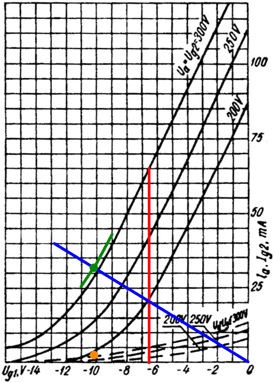
The 150Ω cathode resistor carries the plate and screen current for two tubes, so its equivalent value for one tube is double: 300Ω. If the plate current is 40mA, then according to Ohm's Law the voltage across the cathode resistor is
(1.07)(40mA)(300Ω) = 12.8V
A grid voltage of -12.8V and a plate current of 40mA is one endpoint of the blue line. If there is no plate current the voltage across the cathode resistor is 0V, so the other endpoint represents a 0V grid and 0mA plate current.
If the DC grid bias is -9V, then the cathode is at 9V and the screen-to-cathode voltage is
325V - 9V = 316V
If the grid bias is -10V or -11V, then the screen voltage is 315V or 314V, respectively. These are the endpoints of the green line segments.
The intersection of the blue and green lines is slightly above the plate current curve for a 300V screen (green dot), indicating the DC plate current is 32mA for one tube. If the ratio of screen current to plate current is
5mA / 65mA = 0.077
then the screen current should be
(0.077)(32mA) = 2.5mA
This is born out by the corresponding orange dot placed slightly above the dashed screen current curve, which indicates the screen current is 2.5mA.
Based on this analysis, our estimate of the DC operating point for an average set of tubes is
- a grid bias of -10.2V,
- a screen-to-cathode voltage of 315V,
- a plate-to-cathode voltage of 322V, and
- a cathode current (screen current plus plate current) of 34mA per tube.
Plate and screen dissipations are
(322V)(32mA) = 10.3W
(315V)(2.5mA) = 788mW

|
Guitar Amplifier Electronics: Basic Theory - master the basics of preamp, power amp, and power supply design. |
The screen voltage is only slightly above 300V, so we can use 300V plate characteristics.
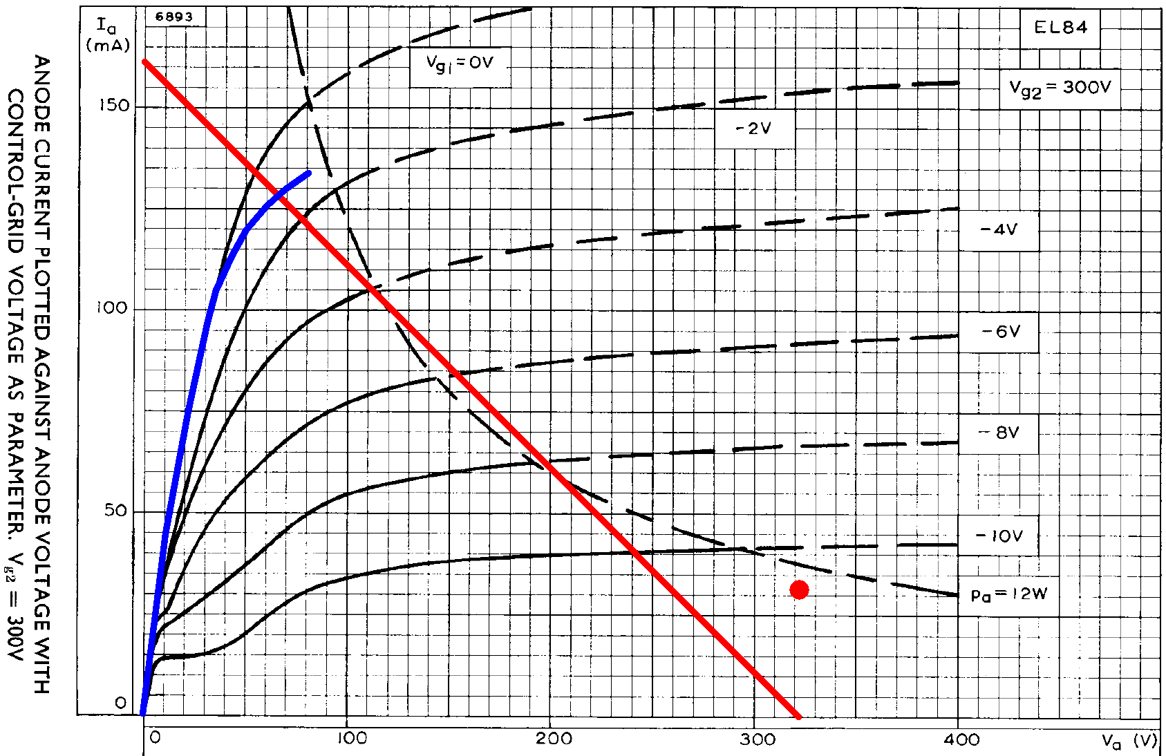
The blue curve is for a 250V screen and 0V grid. If we approximate audio performance by assuming pure Class B operation, we divide the 8kΩ plate-to-plate primary impedance by 4 and plot a 2kΩ load line (red). If the plate voltage swings from 322V down to 0V, the plate current increases from 0mA to
322V / 2kΩ = 161mA
The red load line therefore connects 322V, 0mA and 0V, 161mA. The red dot is the DC operating point.
The blue curve is for a 250V screen. The black curve is for a 300V screen. They act as references for an imagined curve for a 315V screen. The load line crosses it at a plate voltage of about 50V and a plate current of about 135mA, so output power is in the neighborhood of
(322V - 50V)(135mA) / 2 = 18W
At full power, the signal at the grids is 10.2V peak, which is +17.2dBV. This represents power amp input sensitivity.2

|
Fundamentals of Guitar Amplifier System Design - design your amp using a structured, professional methodology. |
Phase Inverter
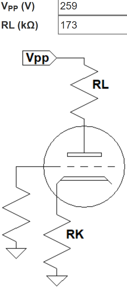
The long tailed pair phase inverter uses a dual 100kΩ potentiometer as the master volume. There is no feedback from the output transformer.
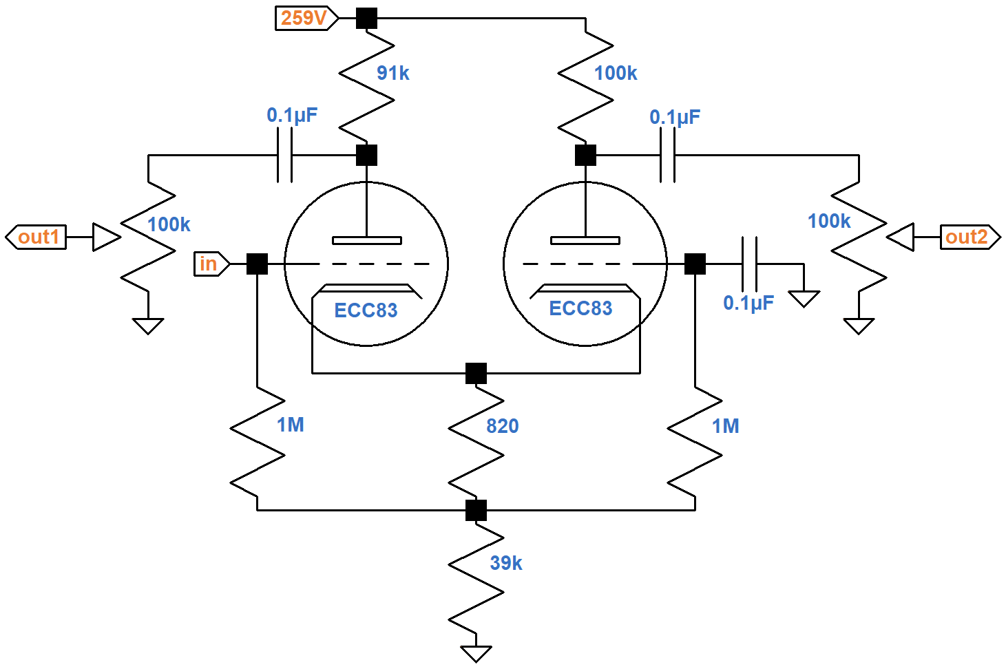
The resistors connecting the cathodes to ground carry the current of two triodes, so for the purposes of determining the DC operating point, the equivalent circuit for one triode doubles the resistor values to 1.64kΩ and 78kΩ, respectively. For the plate load resistor, let's use an average value of 95kΩ. This puts a total of 95kΩ + 78kΩ = 173kΩ plus the bias resistor in series with the tube. According to the 12AX7 calculator, the effective 1.64kΩ bias resistor creates a DC grid bias of -1.2V.
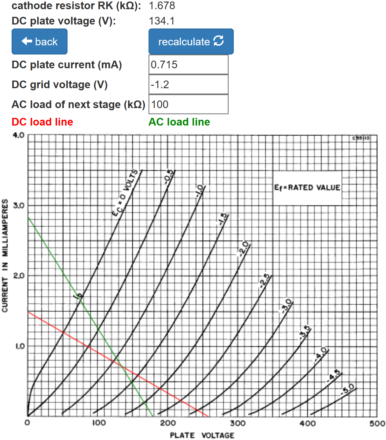
The green AC load line indicates that the plate voltage swings from 75V to 180V. With the master volume at maximum this is considerably more than the 20.4V peak-to-peak swing needed to drive the power amp to full power. The power amp is in overdrive long before the phase inverter. The total DC supply current for two triodes is double the amount shown: 1.4mA.

|
Guitar Amplifier Electronics: Circuit Simulation - know your design works by measuring performance at every point in the amplifier. |
According to the Long Tailed Pair calculator, the inverted and non-inverted gains are well balanced.
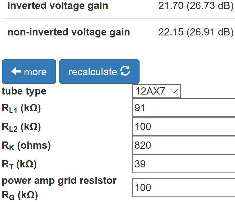
This is attributable to the choice of 91kΩ and 100kΩ for the plate load resistors and a "long" 39kΩ tail.
The Phase Inverter Bass Response calculator shows that the 0.1μF coupling capacitors create a very flat bass response.
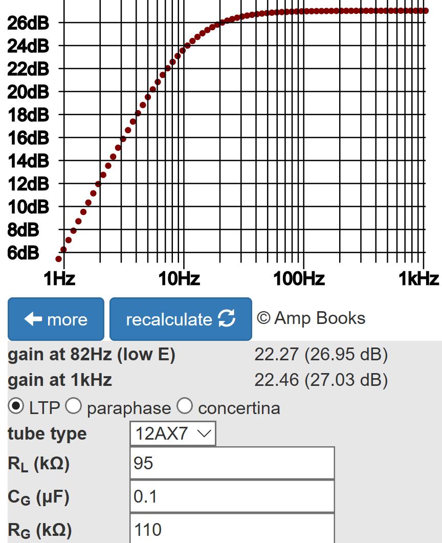
The LTP has 27dB gain, so input sensitivity is
17.2dBV - 27dB = -9.8dBV (458mV peak)
Tone Stack
The AD15 uses a Fender Bassman 5F6-A tone stack but with modified parts values. It is driven by a traditional 12AX7 voltage amplifier with an output impedance3 of 38kΩ instead of the Bassman's low-impedance cathode follower.
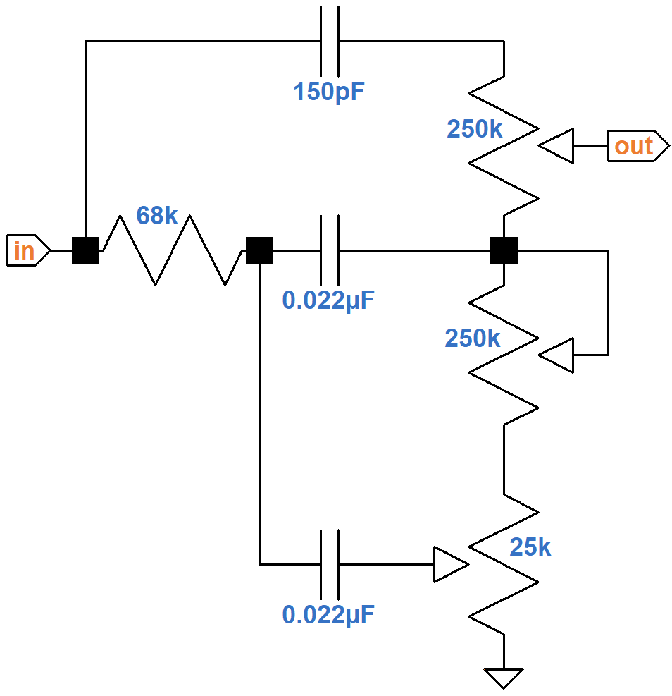
Here is the response using SPICE simulation.4
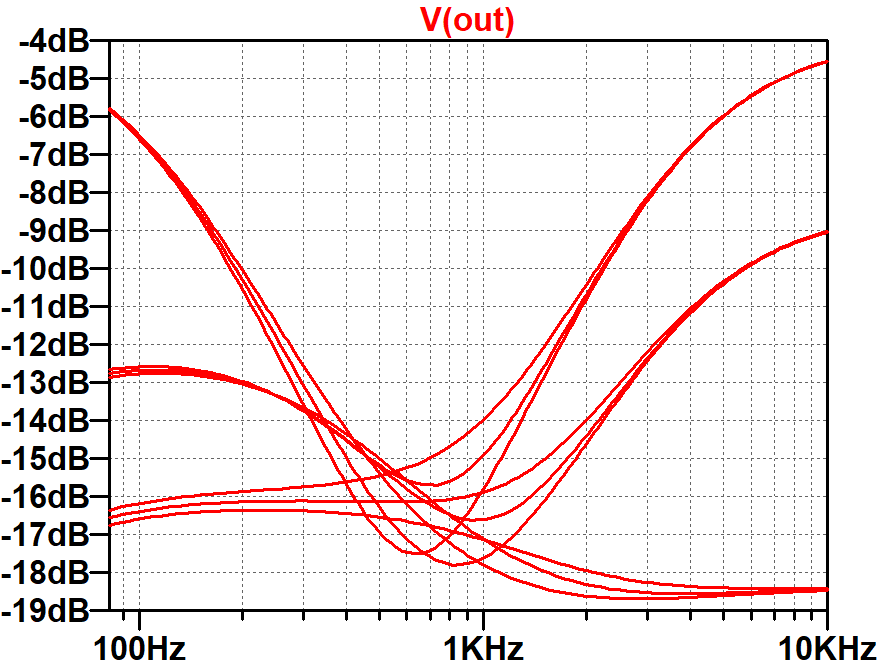
The simulation assumes the driving circuit has an output impedance of 38kΩ and the three controls are at minimum, 50-percent rotation, and maximum for a total of 27 traces. With the controls at noon, scoop is around -17dB, so input sensitivity is
-9.8dBV + 17dB = +7.2dBV (3.2V peak)
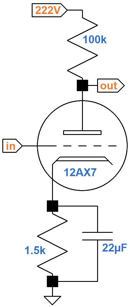
Second Stage Preamp
The design of the second stage, with its 100kΩ plate load resistor and fully bypassed cathode resistor, has become so ubiquitous in guitar amp design that it has even been called a standard 12AX7 voltage amplifier.5
According to the Preamp Gain and Output Impedance calculator, the unloaded gain is 35.8dB.
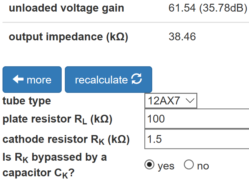
We need the unloaded gain because the attenuation due to the 38kΩ output impedance is included in the SPICE simulation. Input sensitivity is
7.2dBV - 35.8dB = -28.6dBV (53mV peak)
First Stage Preamp
The first stage has two optional capacitors for voicing.6
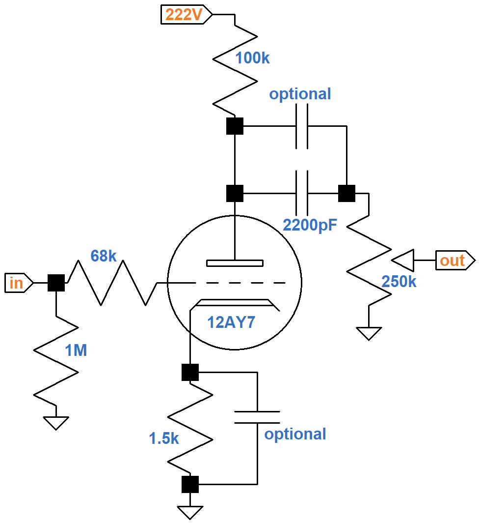
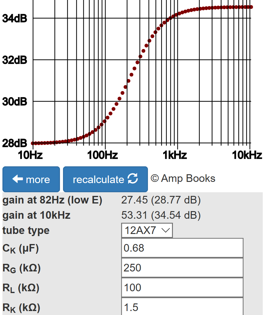
If a 22μF capacitor is used to bypass the cathode resistor, like for the second stage, we get another "standard 12AX7 voltage amplifier." According to the Cathode Bypass Capacitor calculator, if a 0.68uF capacitor is used, the loaded gain varies from 28.8dB for bass to 34.5dB for treble.
Without an optional capacitor in parallel with the 2200pF coupling capacitor, bass attenuation is severe. According to the Coupling Capacitor calculator, there is 10dB attenuation at 82Hz, the lowest note on a guitar with standard tuning, compared to midrange.
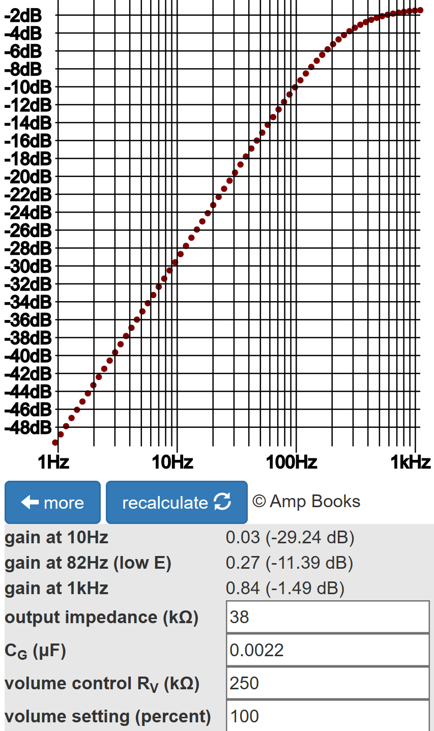
From there gain increases at a rate of 20dB per decade. If a 0.01μF capacitor is placed in parallel with the 2200pF capacitor, bass attenuation is only 1dB.
The gain control inserts 20dB attenuation at 50-percent rotation, 10-percent resistance, so with an unbypassed cathode resistor input sensitivity is
-28.6dBV + 20dB - 28.8dB = -37.4dBV (19mV peak)
This happens to match the Fender Champ 5E1 when its volume control is at maximum. From here the AD15 gain control can be cranked up to maximum for an additional 20dB gain. When the cathode is fully bypassed and the control is set to 50-percent rotation, AD15 sensitivity at the guitar input jack is -43.1dBV (10mV peak). This is well within the capabilities of a single-coil pickup.
References
1Dave Hunter, The British Amp Invasion, (Milwaukee: Backbeat Books, 2017), pp. 167-168.
2Richard Kuehnel, Fundamentals of Guitar Amplifier System Design, (Seattle: Amp Books, 2019), p. 6.
2Richard Kuehnel, Guitar Amplifier Electronics: Basic Theory, (Seattle: Amp Books, 2018), pp. 45-47.
3Richard Kuehnel, Guitar Amplifier Electronics: Basic Theory, (Seattle: Amp Books, 2018), pp. 67-70.
4Richard Kuehnel, Guitar Amplifier Electronics: Circuit Simulation, (Seattle: Amp Books, 2019).
5Richard Kuehnel, Fundamentals of Guitar Amplifier System Design, (Seattle: Amp Books, 2019), pp. 21-22.
6Richard Kuehnel, Fundamentals of Guitar Amplifier System Design, (Seattle: Amp Books, 2019), pp. 114-134.


