Complex Impedance
A resistor with a value of R has an impedance of R ohms, a real number. An ideal inductor has a complex impedance of

where f is the frequency in Hertz and L is the inductance in Henries. It is imaginary because an ideal inductor can only store and release electrical energy. It can't dissipate it as heat like a resistor. Similarly, an ideal capacitor has a complex impedance of

where C is the capacitance in Farads.
Complex Impedance
The components in a guitar amplifier often combine real and imaginary numbers. The choke in a Fender Bassman 5F6-A, for example, has an inductance of 10 Henries. At a frequency of 120Hz (the frequency of AC ripple from a full-wave rectifier in the US) the choke's impedance based on our formula is
j2(3.14)(120)(10) = j7.5k
Because copper wire is not a perfect conductor, the choke also has about 100 ohms of resistance. Thus there are 100 real ohms in series with 7.5k imaginary ohms. We express this as the complex impedance
Z = 100+j7.5k
Let me get this straight. A theoretically perfect Bassman choke would have no winding resistance. It would thus be purely inductive and its impedance would be purely imaginary: Z = j7.5k. The windings in an actual Bassman choke are not perfect conductors, so they add a small amount of real resistance: Z = 100+j7.5k. So in an imaginary world the impedance is purely imaginary and in the real world it is only mostly imaginary. Clear as mud? OK, let's move on.

|
Guitar Amplifier Electronics: Fender Deluxe - from TV front to narrow panel to brownface to blackface Reverb |
Magnitude and Angle
We can plot complex numbers by using the X-axis to represent the real component and the Y-axis to represent the imaginary component.
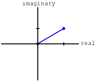
A complex number has both a magnitude, which is a measure of how big it is, and an angle, which describes how its real and imaginary components are related. For guitar amplifier design we are usually interested only in the magnitude, because often it represents the amount of voltage gain or attenuation. The angle is sometimes also important in feedback caculations.
|
Guitar Amplifier Electronics: Basic Theory - master the basics of preamp, power amp, and power supply design. |
The magnitude of a complex number A+jB, representing the distance from the origin, is

The angle between the positive real axis and the line segment denoting the complex number is

where tan-1 is the inverse tangient.
|
Fundamentals of Guitar Amplifier System Design - design your amp using a structured, professional methodology. |
Problem
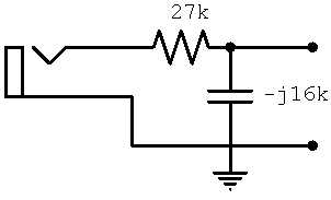
There is an effective resistance of 27k connecting the Fender Harvard 5F10 high-gain input jack to the grid of the preamp tube. If the 6AT6 preamp tube input impedance at 20kHz is -j16k due to Miller capacitance, what is the magnitude of the output voltage compared to the sinewave input voltage?
Solution
The input circuit and the Miller capacitance combine to form a voltage divider where Z1 = 27k and Z2 = -j16k. The output voltage is

so the relationship is described by the complex number

First we divide the numerator and the denominator by 1000.

Then we multiply the numerator and the denominator by 27+j16 to eliminate the appearance of j in the denominator, as will be seen in the next step.

We expand the terms.

We note that the two middle terms in the denominator cancel each other, eliminating j. In the numerator we separate every appearance of j as if it were a variable.

Big drumroll please! In this important step we replace any occurrence of j2 by (-1).

We multiply the individual products and simplify.

We compute the magnitude by adding the squares of the real and imaginary components and taking the square root of the result.

We conclude that for a 20kHz sinewave input signal, the output signal has an amplitude that is 51 percent of the input signal amplitude. The phase angle is

Thus the output sinewave lags the input sinewave by 59 degrees.

|
From system design concepts to individual stage operation, an all-new examination of Bassman electronics. |
