The Voltage Divider
For a single resistor with a voltage across it, Ohm's Law is quite an impressive tool. Put a few resistors together in series, however, and things get even more interesting! The total resistance of resistors in series is simply the sum of their individual resistances. By combining this concept with Ohm's Law we can design one of the most commonly used circuits in a guitar amplifier: the voltage divider.
Problem
Consider the power supply of a Mesa Boogie Bass 400 amplifier. It uses two 150kΩ resistors in series to equalize the voltage across the filter capacitors and to act as bleed resistors that slowly discharge the capacitors when the amplifier is turned off. (If only all amplifiers were designed this way - it would be a much safer world!) The total voltage across both resistors is 534V. What is the voltage across each individual resistor?
Solution
The total resistance across both resistors is
150kΩ + 150kΩ = 300kΩ
According to Ohm's Law, the current passing through the resistors is
534V / 300kΩ = 1.78mA
Thus 1.78mA passes through each of the resistors individually. By applying Ohm's Law once more, we get the voltage across one resistor:
(1.78mA)(150kΩ) = 267V
OK, I admit this was an easy problem. Just looking at the two equal resistors you can surmise that half the voltage must be across each one. But what would be the voltages across two unequal resistors?

|
Guitar Amplifier Electronics: Fender Deluxe - from TV front to narrow panel to brownface to blackface Reverb |
The Voltage Divider
A voltage divider is often used to attenuate a signal by a prescribed amount. We often see them in guitar amplifier input circuits, for example, where they attenuate the signal to give the guitar player a low-gain input jack. They are also used in the second stage of a paraphase inverter to equalize the amplitudes of the two output phases. Other guitar circuits may not appear to be voltage dividers at first, but we frequently discover that at certain frequencies the components effectively create one. The voltage divider thus represents an essential tool of guitar amplifier design.
Problem
Consider the second stage paraphase inverter of the Gibson GA-20T amplifier. An input signal is applied across 220kΩ and 4.7kΩ resistors in series. The output voltage is the voltage across the 4.7kΩ resistor. Given that the input signal is 1V, what is the output voltage?
Solution
The total resistance of both resistors in series is 224.7kΩ. This means that according to Ohm's Law the current is
1V / 224.7kΩ = 0.00445mA
This current passes through the 4.7kΩ resistor, so according to Ohm's Law, the voltage across it is
(0.00445mA)(4.7kΩ) = 21mV
So the input is 1V and the output is 21mV. The output is thus only 2.1 percent of the input. This is quite a bit of attenuation and not a random value picked by the engineers in Kalamazoo. The resistor values were chosen to reduce the input voltage by exactly this amount.

|
Guitar Amplifier Electronics: Basic Theory - master the basics of preamp, power amp, and power supply design. |
Notice that we computed the output voltage in two separate steps. First we computed the current that passes through both resistors. Then we used this current to determine the output voltage. We really weren't interested in the current. We just needed it as an intermediate step. Let's combine the two steps into one equation to simplify the calculation. Looking at our procedures in reverse, the output voltage is
(0.00445mA)(4.7kΩ) = 21mV
and the current is
0.00445mA = 1V / 224.7kΩ
We combine these into a single equation:
(1V / 224.7kΩ)(4.7kΩ) = 1V(4.7kΩ / 224.7kΩ) = 21mV
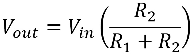
So the output voltage is equal to the input voltage times the resistance across the output divided by the total resistance in series. This works for any combination of two resistors R1 and R2, as shown in this circuit:
The output voltage is equal to the input voltage times the output resistor R2 divided by the total resistance R1+R2. This is the fundamental Principle of a voltage divider.

|
Fundamentals of Guitar Amplifier System Design - design your amp using a structured, professional methodology. |
Problem
The Valco 6550TR bass input jack is connected to the grid of the preamp tube via a voltage divider, where R1=100kΩ and R2=470kΩ. By what percentage is the input voltage attenuated?


