Circuit Analysis of the Vox AC15 Pentode Preamp and Power Amp
The Vox AC15 is a highly revered amp, capable of delivering amazing sounds at a power level that won't crack wall plaster.
"All told, a rare combination of qualities that together create an amp that is unparalleled in the studio and pure bliss to play cranked up in clubs and on small and medium stages." 1 -Dave Hunter
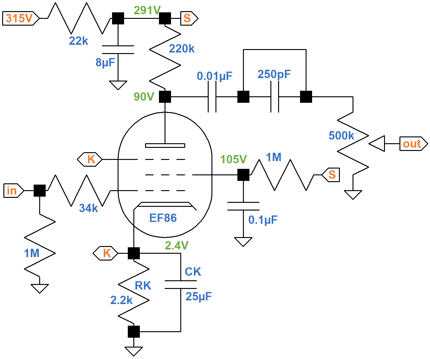
First Stage Pentode Preamp
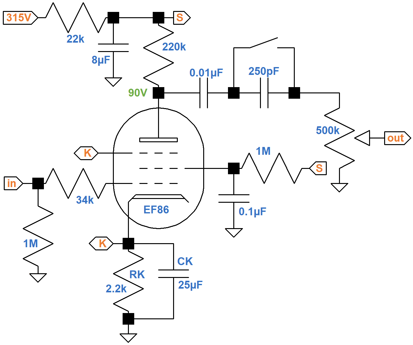
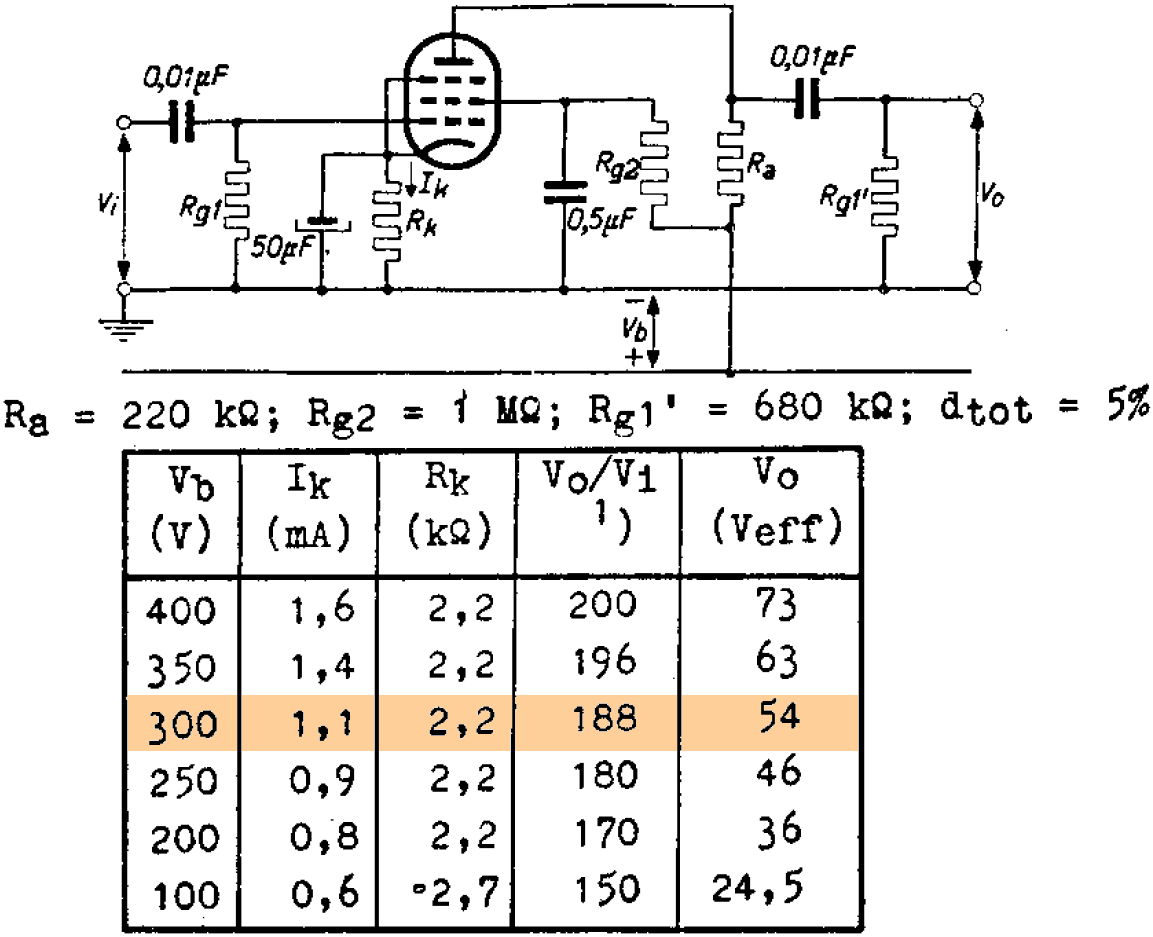
The first stage voltage amplifier is essentially identical to an example in a Philips EF86 data sheet, which has a voltage gain of 188.

|
Guitar Amplifier Electronics: Fender Deluxe - from TV front to narrow panel to brownface to blackface Reverb |
EF86 DC Conditions
If the DC cathode current is 1.1mA, matching the example, then the voltage drop across the power supply's 22kΩ ripple filter resistor is
(1.1mA)(22kΩ) = 24V
The plate supply voltage is therefore 291V, close to the 300V for the data sheet example. Vox measures 90V at the plate, so according to Ohm's Law the DC plate current is
(291V - 90V) / 220kΩ = 0.91mA
Subtracting this from the cathode current gives us a screen current of 0.19mA and a ratio of plate current to screen current of about 5 to 1, which is reasonable. The cathode voltage is
(1.1mA)(2.2kΩ) = 2.4V
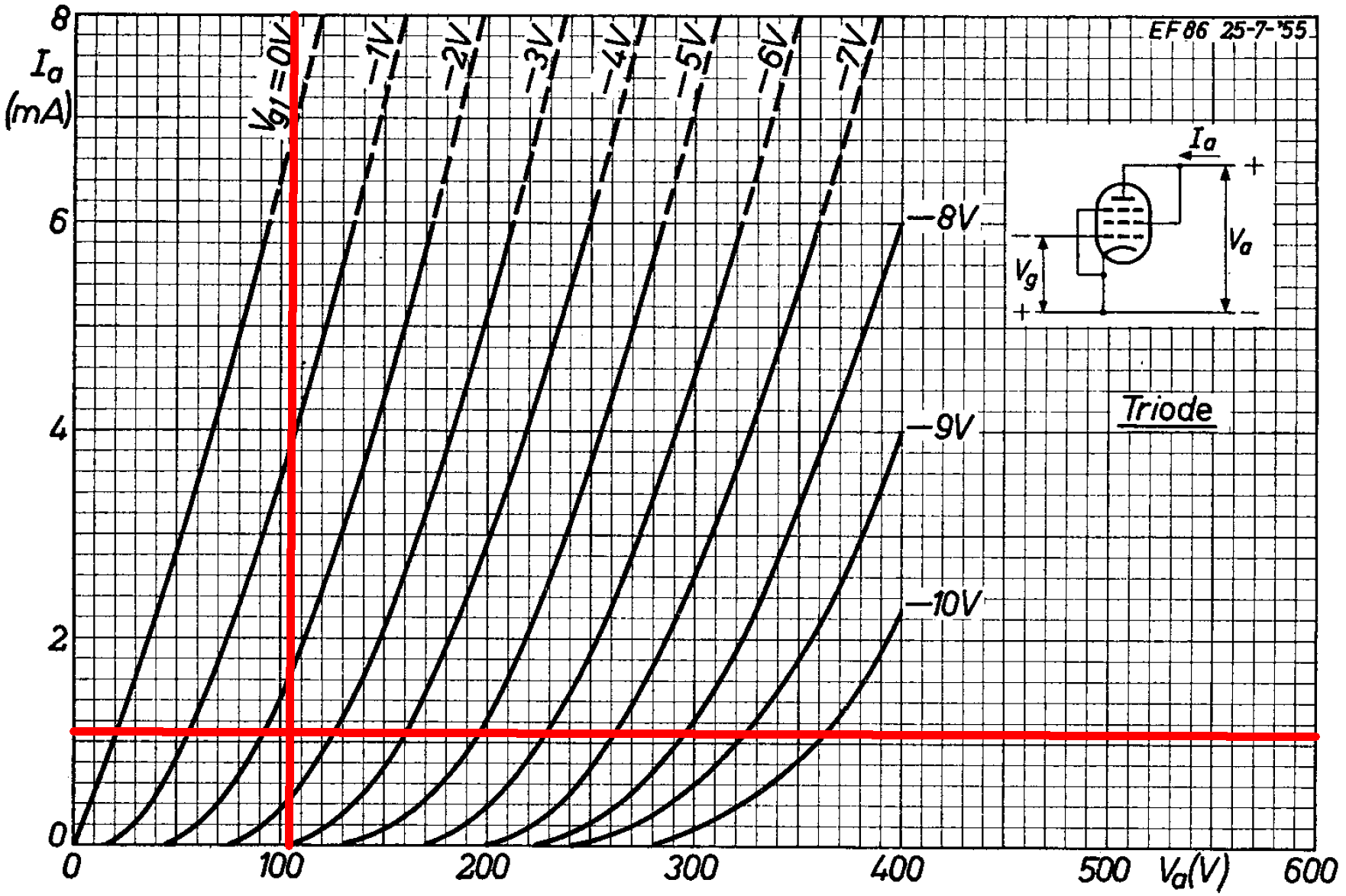
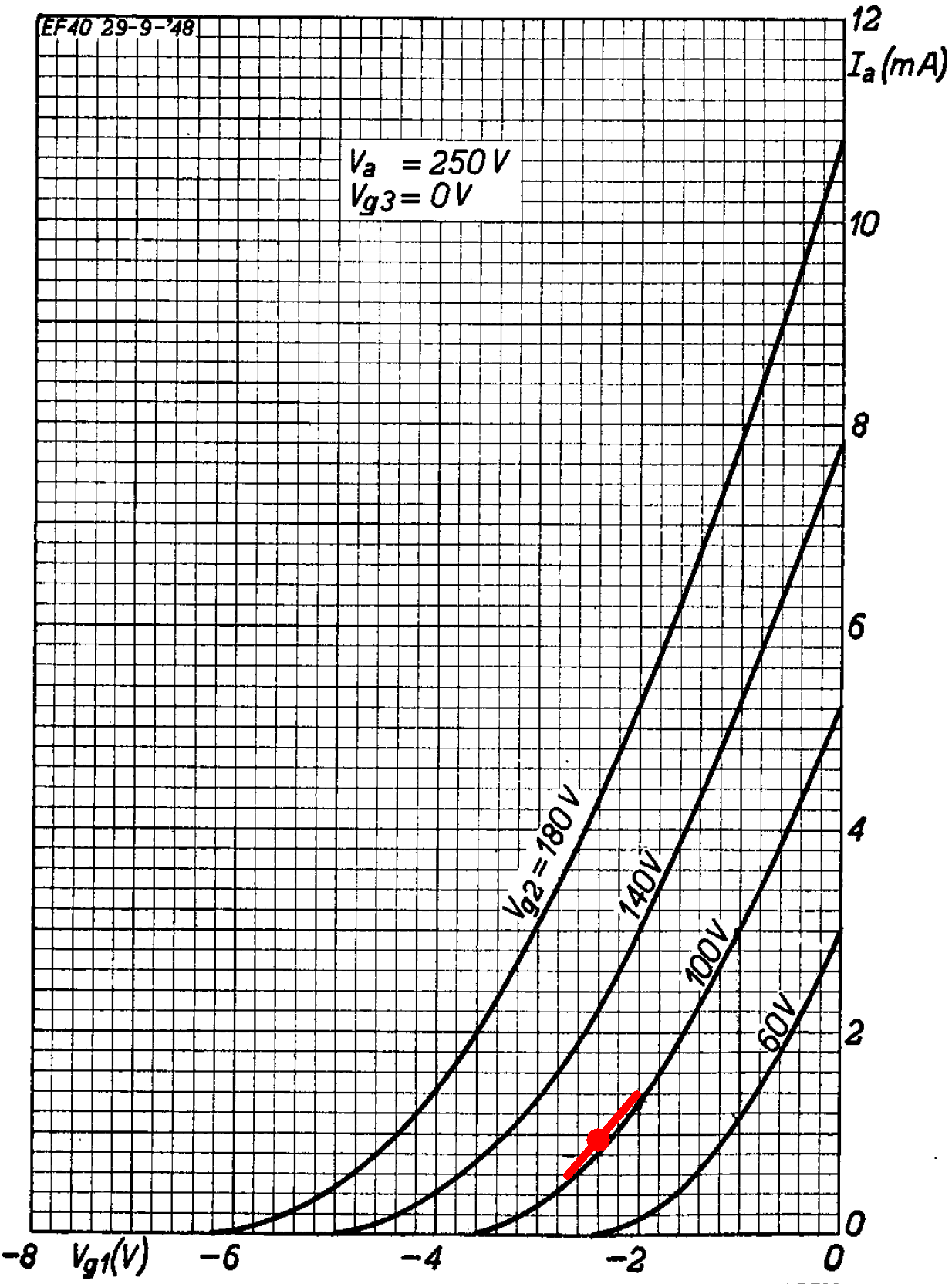
According to the plate transfer characteristics, for a -2.4V grid-to-cathode voltage and a plate current of 0.91mA, the screen voltage is about 105V.
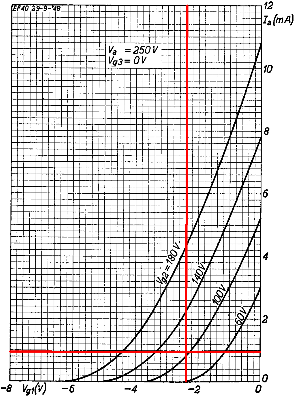
Since the plate and screen voltages are nearly the same, we can use the triode-connected curves to check these results. For these curves we use the screen voltage as the "plate voltage" because the screen has a much greater influence on electron flow.2 A "plate" voltage of 105V and a "plate" current of 1.1mA intersect an imagined curve for a -2.4V grid.
According to Ohm's Law, the current through the screen resistor should be
(291V - 105V) / 1MΩ = 0.19mA
This matches our earlier calculation, so DC operating conditions are as expected.

|
Guitar Amplifier Electronics: Basic Theory - master the basics of preamp, power amp, and power supply design. |
First Stage Audio Performance
The data sheet uses 0.5μF for the screen bypass capacitor, compared to 0.1μF for the AC15. The break frequency is
1 / [2π(1MΩ)(0.1μF)] = 1.6Hz
This is well below audio, so the screen is fully bypassed - there is no negative feedback from screen degeneration, when screen voltage varies in response to the audio signal to reduce gain.
The data sheet recommends a 50μF cathode bypass capacitor. The AC15's value is 25μF. The effective cathode impedance is equal to the 2.2kΩ cathode resistor in parallel with the reciprocal of the tube's transconductance. According to the plate transfer characteristics, a grid voltage swing of 0.7V creates a plate voltage swing of 0.8mA.
The transconductance at the DC operating point is therefore approximately
0.8mA / 0.7V = 1.14mS
The reciprocal is
1 / 1.14mS = 875Ω
The effective cathode impedance is therefore
2.2kΩ || 875Ω = 626Ω
The break frequency for the bypass capacitor is
1 / [2π(626Ω)(25μF)] = 10Hz
This is well below audio, so a 25μF value is sufficient to fully bypass the cathode resistor. Voltage gain therefore matches the data sheet: 188 (45dB). Good luck trying to get this much gain from a triode!
According to the plate transfer characteristics, The grid can swing from -3.6V to 0V, which is -1.2V to +2.4V relative to the DC grid bias.
The peak output from a single-coil pickup is about 100mV, so the first stage has plenty of headroom.

|
Fundamentals of Guitar Amplifier System Design - design your amp using a structured, professional methodology. |
The plate resistance of a pentode is very high, so the output impedance is only slightly less than the plate load resistor value: 220kΩ. With the brilliance switch closed, the coupling capacitance is equal to 0.01μF. When open, it is equal to 0.01μF and 250pF in series:3
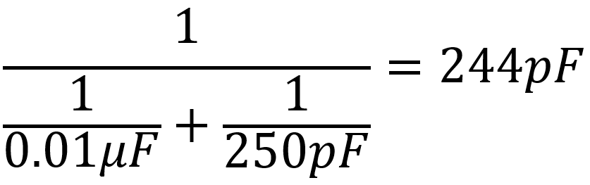
This is an extremely small value for a coupling capacitor, so we can expect aggressive bass cut when the switch is open. The coupling capacitance combines with the output impedance and volume control to create a high-pass filter. According to the Coupling Capacitor calculator, there is a dramatic difference in bass cut depending on switch position.
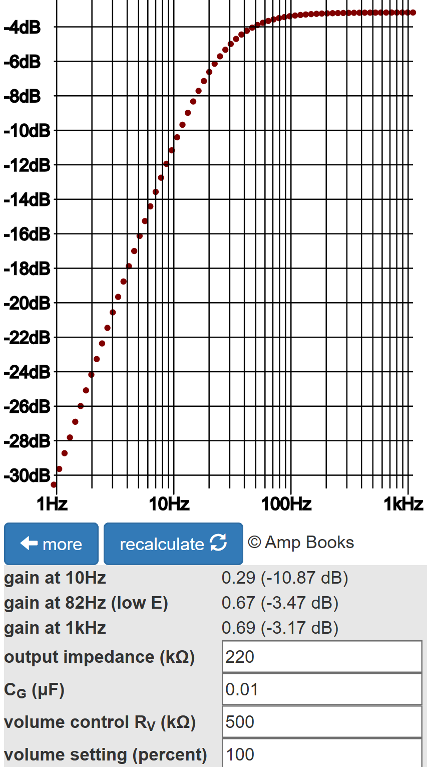
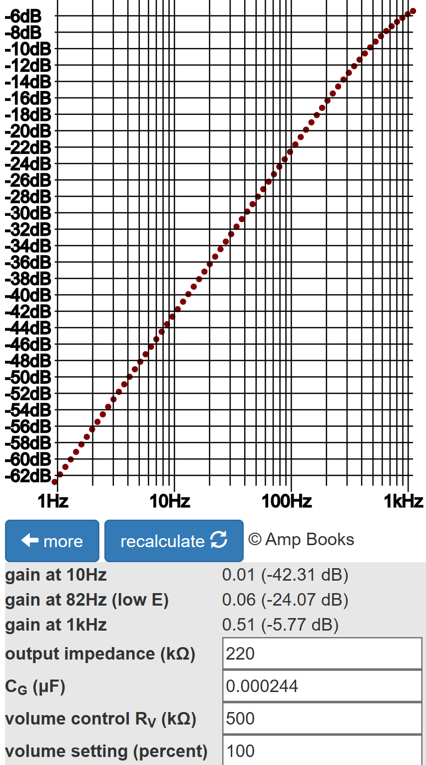
With the switch closed, there is 3.2dB attenuation due to the voltage divider formed by the output impedance and the volume control. The 0.01μF capacitor is essentially a short circuit for audio frequencies - there is only 0.3dB attenuation at 82Hz compared to 1kHz. (82Hz is the lowest note on a guitar with standard tuning.) With the switch open, the gain from bass to middle frequencies increases at a rate of 20dB per decade. The break frequency is
1/ [2π(220kΩ + 500kΩ)(244pF)] = 884Hz

|
Guitar Amplifier Electronics: Circuit Simulation - know your design works by measuring performance at every point in the amplifier. |
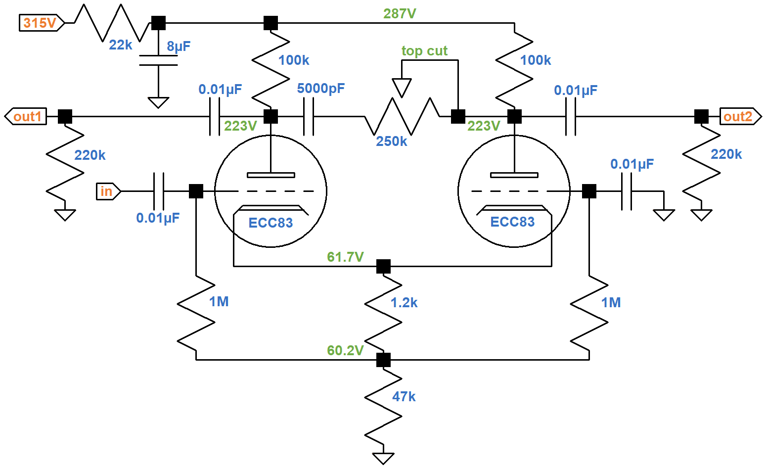
Phase Inverter DC Operating Conditions
The phase inverter is a classic long-tailed pair.
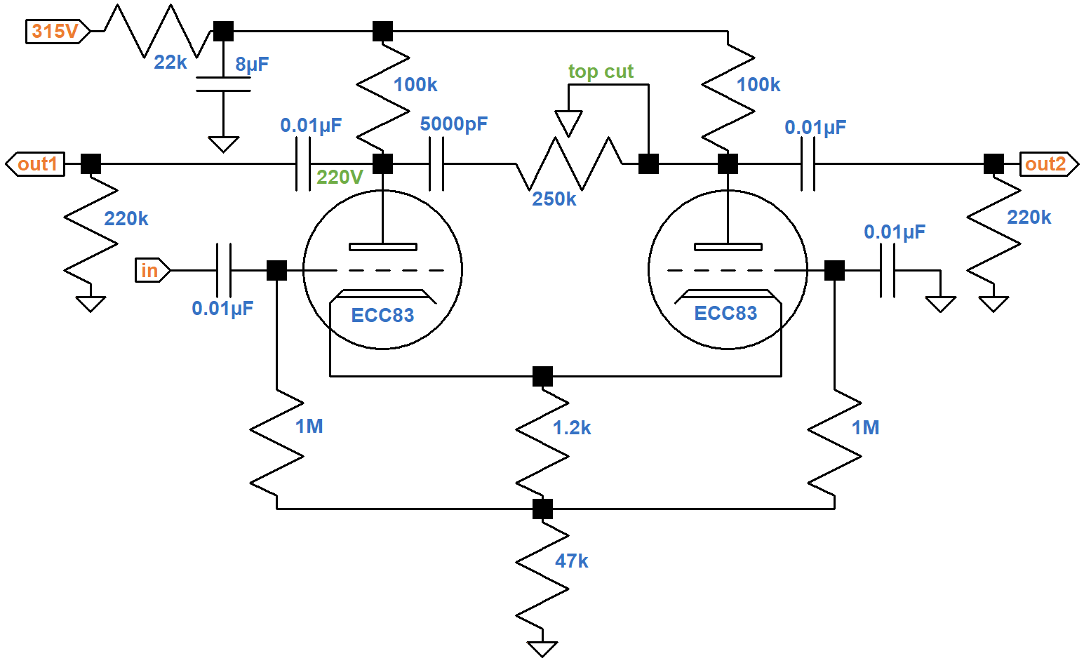
Under DC conditions, all capacitors are open circuits. The 22kΩ ripple filter resistor, 1.2kΩ cathode resistor, and 47kΩ tail resistor carry the current of two triodes, so the equivalent values for one triode are double: 44kΩ, 2.4kΩ, and 94kΩ, respectively.
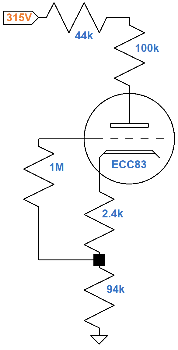
If the plate current is zero, the plate-to-cathode voltage is 315V. If the plate-to-cathode voltage is zero, then according to Ohm's Law the plate current is
315V / (44kΩ + 100kΩ + 2.4kΩ + 94kΩ) = 1.31mA
These are the endpoints of the red line shown here on the plate characteristics.
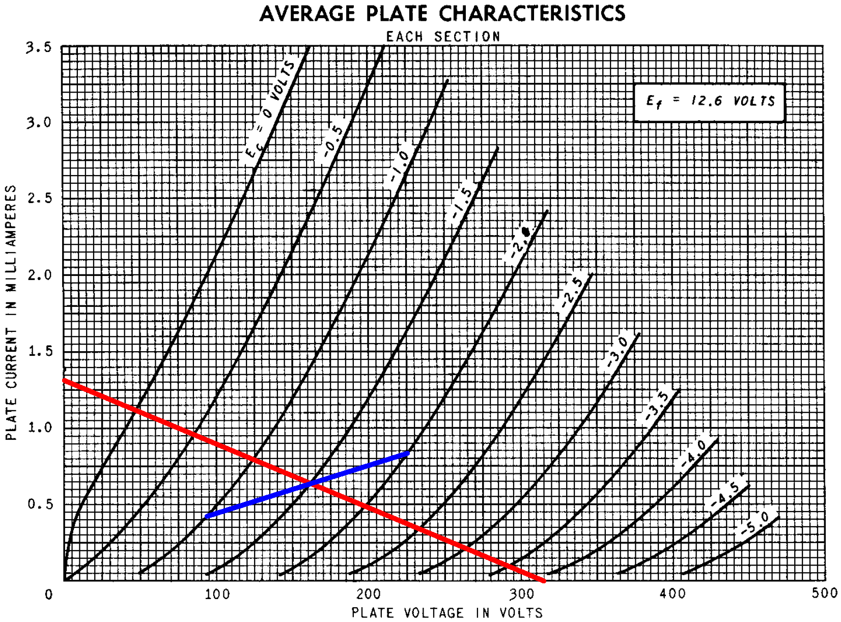
According to Ohm's Law, the voltage across the 2.4kΩ resistance is the product of the resistance and the current through it. If the grid-to-cathode voltage is -1V, -1.5V, or -2V, the plate current is
1V / 2.4kΩ = 0.42mA
1.5V / 2.4kΩ = 0.63mA
2V / 2.4kΩ = 0.83mA
These three points define the blue line segments that appear to intercept the red line at a plate current of 0.64mA, a plate-to-cathode voltage of 161V, and a grid-to-cathode voltage of -1.5V. These values define the DC operating point.
According to Ohm's Law, the voltage drop across each resistance is the resistance times the current, so 0.64mA through the 44kΩ, 100kΩ, 2.4kΩ, and 94kΩ resistances creates voltage drops of 28.2V, 64V, 1.5V, and 60.2V. As a check, the sum of these voltage drops and the 161V between the plate and cathode equals 315V. The estimated plate-to-ground voltage is 223V for an average 12AX7. Vox measures 220V.
Phase Inverter AC Operating Conditions
For audio signals, each 100kΩ plate load resistor and 220kΩ grid leak are in parallel for an effective AC plate load of 69kΩ. For the plate current to swing from its DC value of 0.64mA to a value of zero, the plate voltage must increase by
(0.64mA)(69kΩ) = 44V
relative to its DC value of 161V. The green AC load line connects the DC operating point to an endpoint defined by a plate voltage of 205V and a plate current of 0mA.
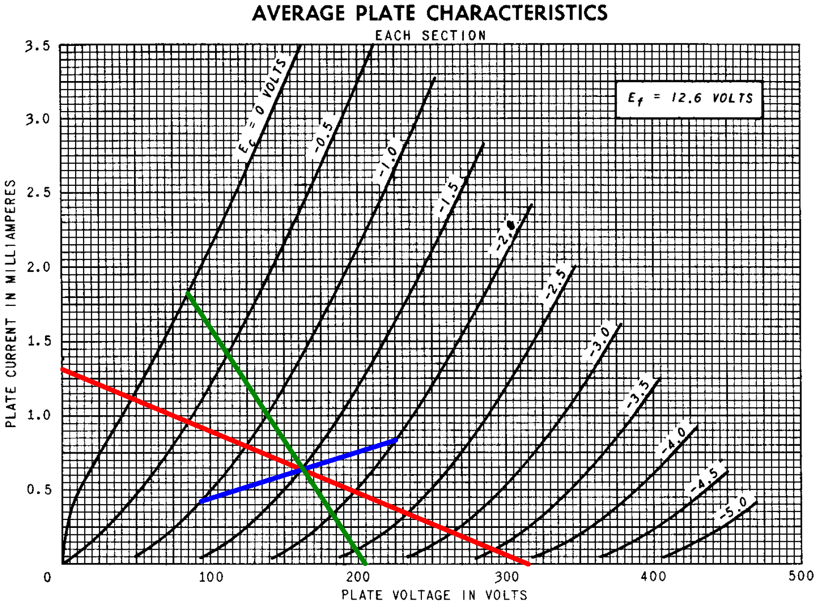
The AC load line shows that the plate voltage can swing by +44V to -76V from the DC operating point. This is much more than the range needed to drive the power amp to full power. The power amp therefore breaks into overdrive long before the phase inverter.
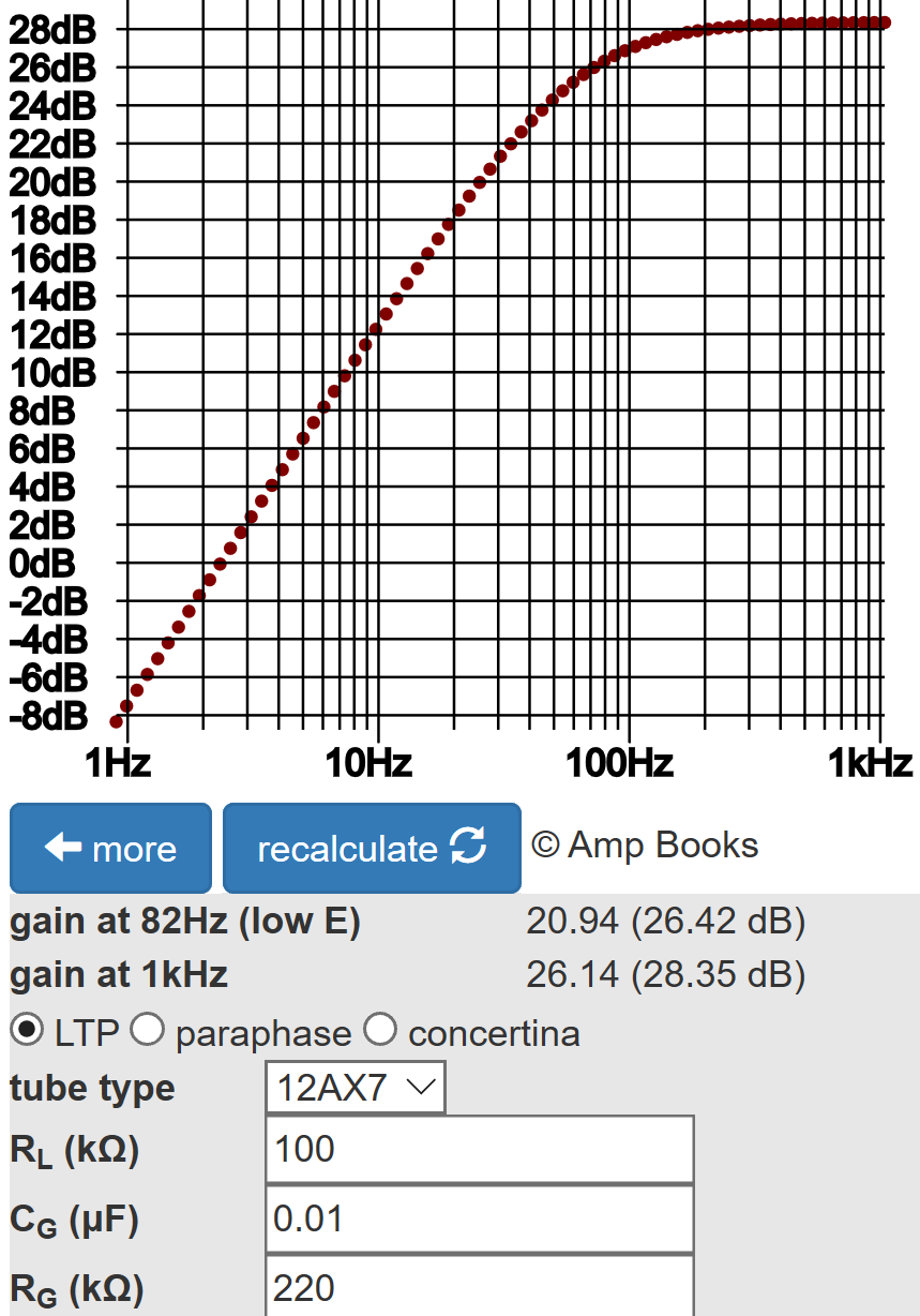
The Long Tailed Pair calculator shows that for a 47kΩ tail the output gains are well balanced at about 28dB.
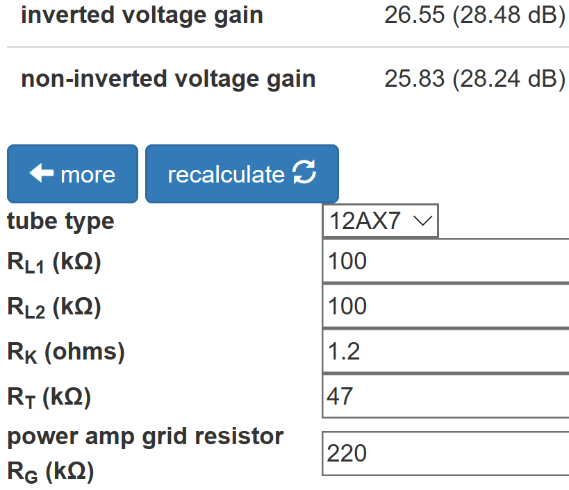
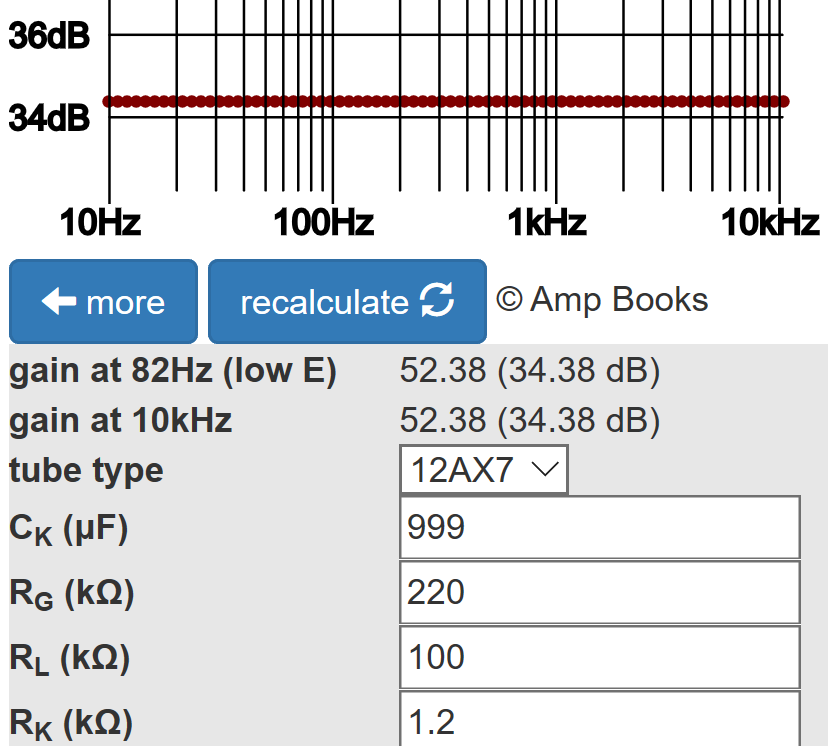
For comparison, according to the Cathode Bypass Capacitor calculator a typical 12AX7 voltage amplification stage has about 6dB more gain.
This is because the grid-to-cathode voltage swing for the LTP is only about half the input grid-to-ground voltage swing.
According to the Phase Inverter Bass Response calculator, The 0.01μF coupling capacitors create about 2dB attenuation at 82Hz.
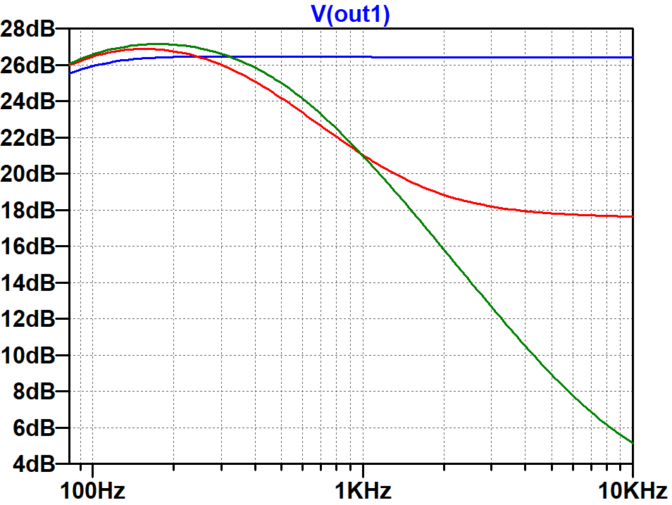
Here are the results of a SPICE AC analysis simulation4 for one output with the "top cut" control set to zero, 10-percent, and 100-percent resistance.
The Power Amp
The power amp has two EL84 pentodes in push-pull with cathode bias.
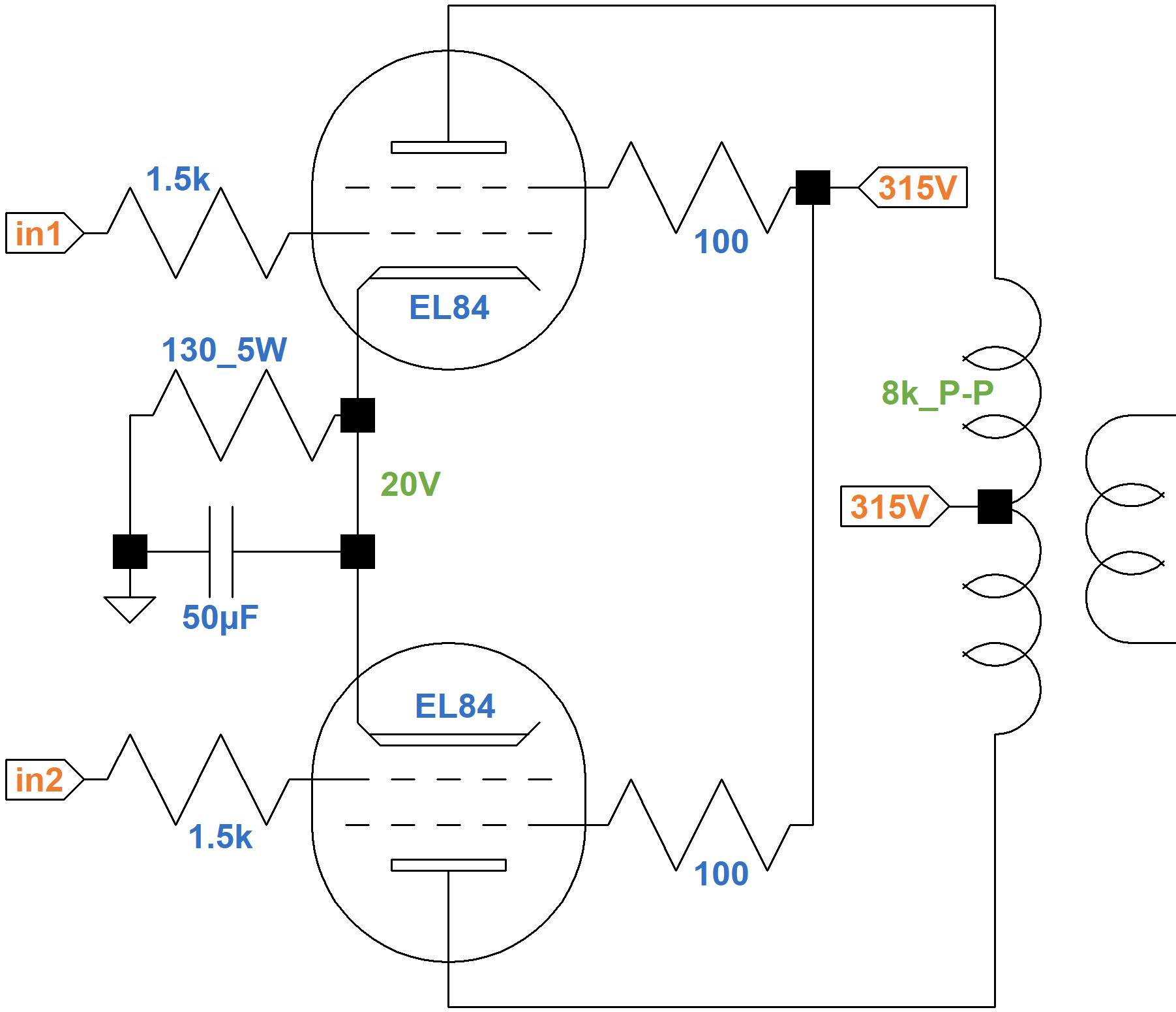
Because the screen and plate voltages are nearly the same, we can use EL84 triode-connected curves to determine the DC operating point. The 100Ω screen resistors protect the tube during overdrive when screen current can be high. At idle, there is only a small voltage drop across them, so we can assume that the screen-to-ground voltage is 315V and that the plate-to-ground voltage is only slightly less than 315V due to DC winding resistance in the transformer. (Vox measures 310V.) The triode-connected tube's "plate current" represents the sum of the plate current and screen current, i.e. the total current that passes through the 130Ω cathode resistor. The current through the resistor is from two tubes, so the equivalent resistance for one tube is 260Ω. If the cathode voltage is 10V or 12.5V, then according to Ohm's Law the plate current is
10V / 260Ω = 38mA
12.5V / 260Ω = 48mA
In terms of grid voltage and plate current, the endpoints of the red line shown here at the far right are -10V, 38mA and -12.5V, 48mA.
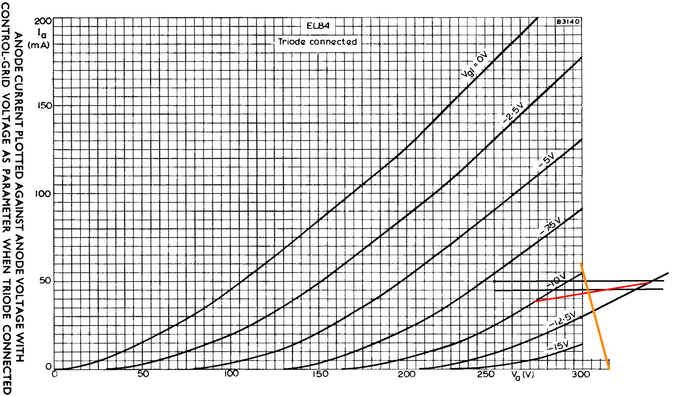
From another perspective, if no current flows through the cathode resistor, there is no voltage across it and the plate-to-cathode voltage is 315V. If the plate current is 60mA, on the other hand, then the cathode voltage is
(60mA)(260Ω) = 15.6V
The DC plate voltage is then 299.4V. These endpoints create the orange line. The intersection of these perspectives represents our estimate of the DC operating point for an average set of tubes:
- a grid bias in the neighborhood of -11.5V,
- a screen-to-cathode voltage of 303V, and
- a cathode current (screen current plus plate current) of 44mA per tube.
Let's make another estimate using a different approach. A Sovtek EL84 data sheet includes plate and screen transfer characteristics when both the plate and screen are at 300V. (A Mullard data sheet has no transfer characteristics and a 6BQ5 data sheet only has curves for 250V and 210V screens.) Using the upper solid curve for plate current and the upper dashed curve for screen current, we see that for a -6.6V grid, the plate current is 65mA and the screen current is 5mA, as depicted by where the red line crosses the two curves.
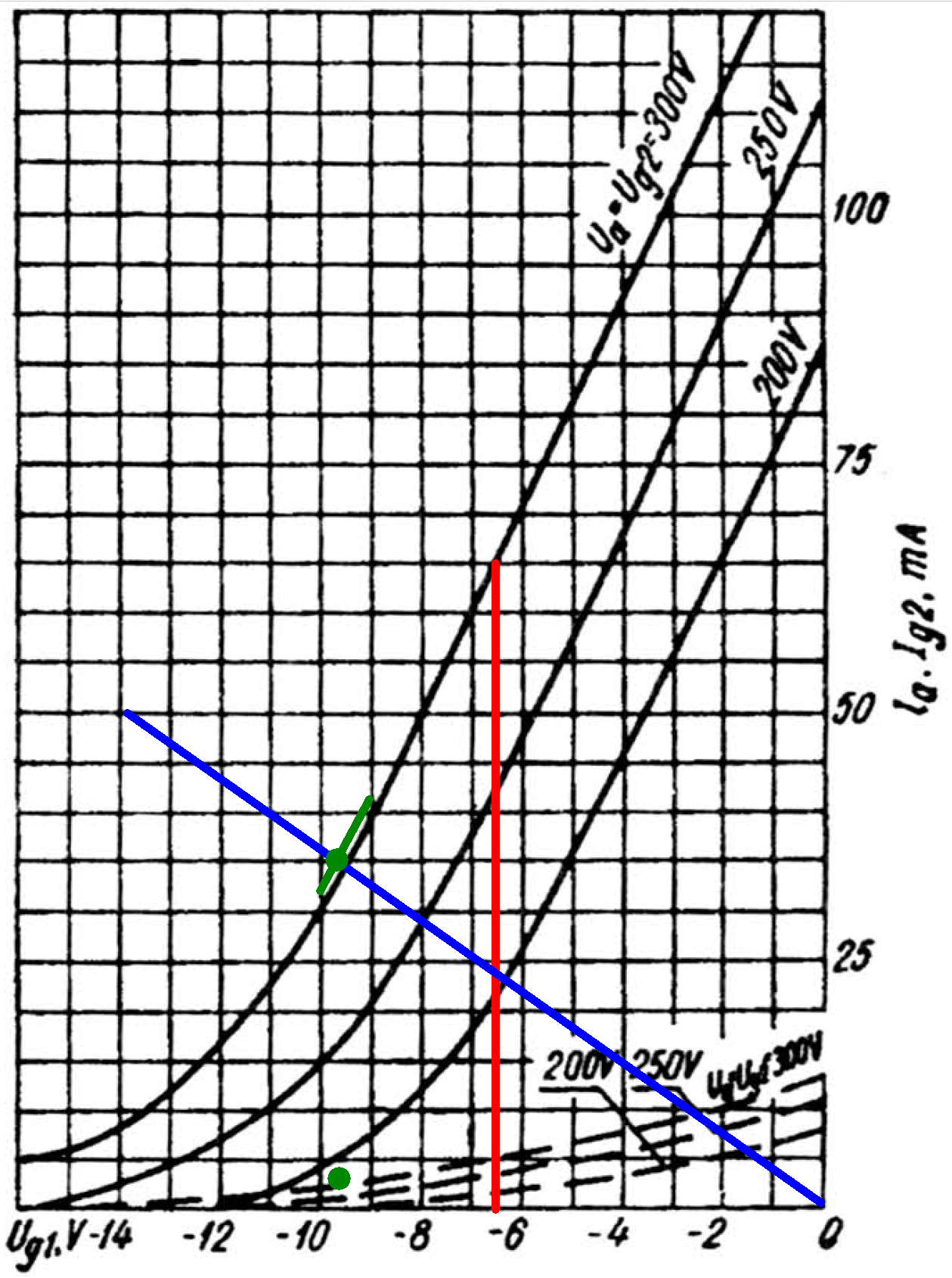
The cathode current is their sum: 70mA. Assuming the ratio of plate current to screen current is approximately constant, then the ratio of cathode current to plate current is constant:
(70mA) / (65mA) = 1.07
If the plate current is 50mA, then according to Ohm's Law the voltage across the cathode resistor is
(1.07)(50mA)(260Ω) = 13.9V
A grid voltage of -13.9V and a plate current of 50mA is one endpoint of the blue line. If there is no plate current the voltage across the cathode resistor is 0V, so the other endpoint represents a 0V grid and 0mA plate current.
If the DC grid bias is -10V, then the cathode is at 10V and the screen-to-cathode voltage is 315V - 10V = 305V. If the grid bias is -9V, then the screen voltage is 306V. These are the endpoints of the green line.
The intersection of the blue and green lines is slightly above the plate current curve for a 300V screen (green dot), indicating the DC plate current is 35mA for one tube. A corresponding green dot is placed slightly above the dashed screen current curve, which indicates the screen current is 3mA.
Based on this analysis, this is our estimate of the DC operating point for an average set of tubes (previous estimates are in parentheses):
- a grid bias in the neighborhood of -9.6V (-11.5V),
- a screen-to-cathode voltage of 305V (303V), and
- a cathode current (screen current plus plate current) of 38mA (44mA) per tube.
These estimates are well within the plus-or-minus 20-percent world of vacuum tube guitar amp design.
The parts values and DC conditions are essentially identical to a Class a AB example in an EL84 data sheet, which also uses an 8kΩ plate-to-plate primary impedance for the output transformer.
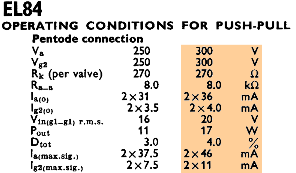
The same example is included in a 6BQ5 data sheet.
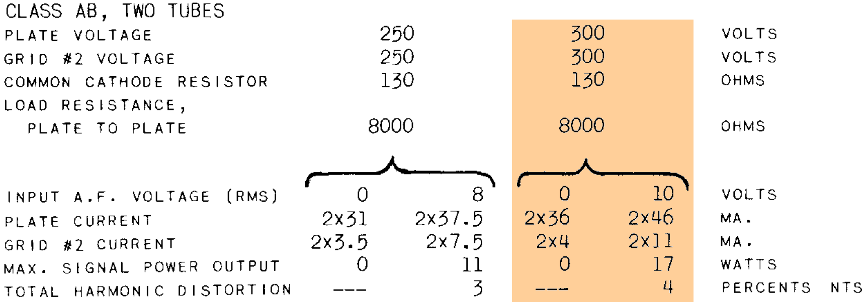
According to the data sheets, "maximum signal power output" is 17 watts, which is generally what we expect from an AC15.5
If we approximate audio performance by assuming pure Class B operation, we divide the 8kΩ plate-to-plate primary impedance by 4 and plot a 2kΩ load line. If the plate voltage swings from 300V down to 0V, the plate current increases from 0mA to
300V / 2kΩ = 150mA
The red load line therefore connects 300V, 0mA and 0V, 150mA.
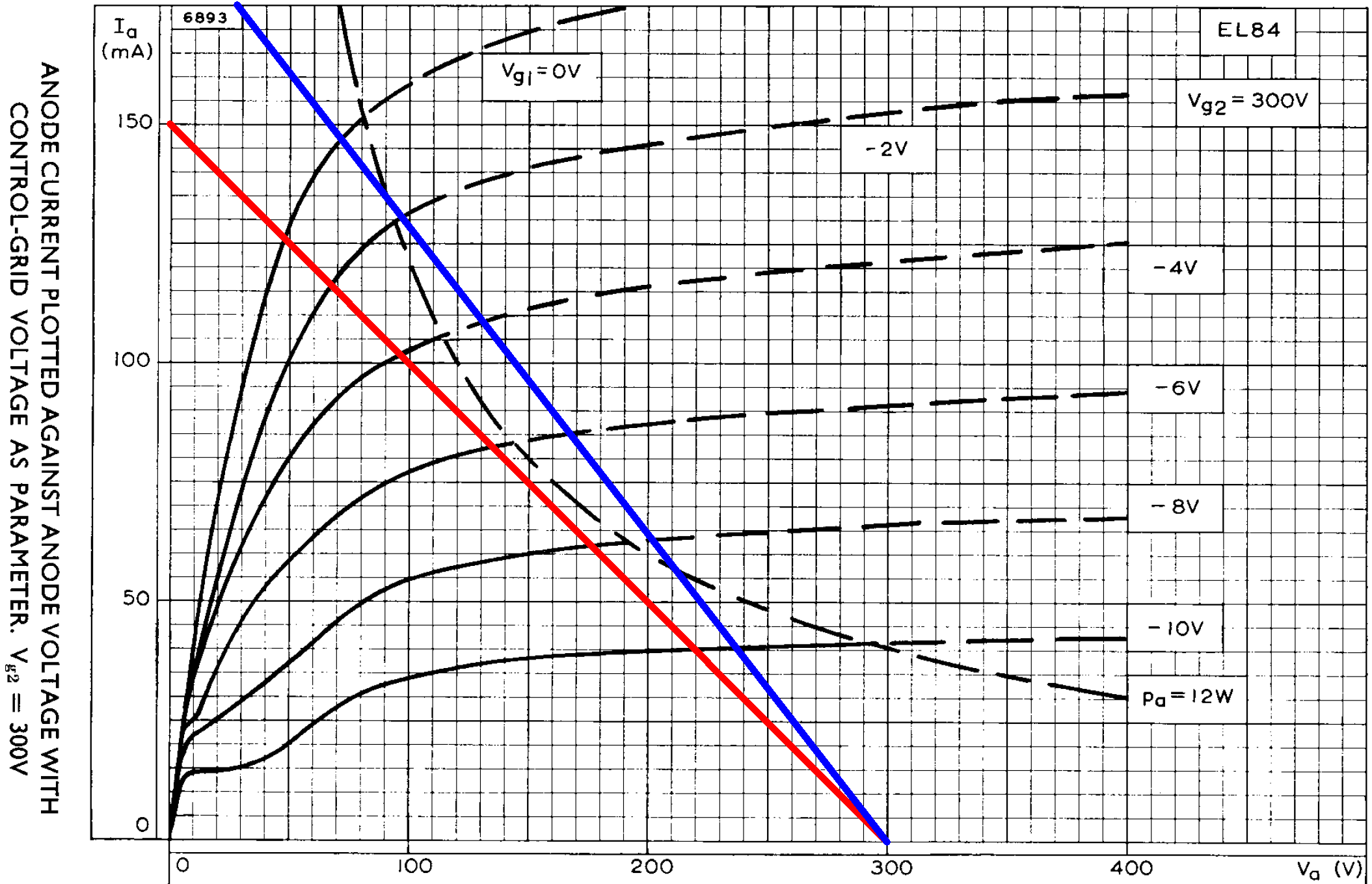
The load line intercepts the curve for a 0V grid at a plate voltage of 48V and a plate current of 127mA. Output power is therefore approximately
(300V - 48V)(127mA) / 2 = 16W
Compared to beam power tetrodes like the 6V6, pentodes do not have sharply defined knees. Nevertheless, the load line appears to intercept the 0V curve just below what we might call the knee. This is textbook audio design, which is what we expect from a data sheet example.
Hammond markets its 1750Y transformer as an AC15 replacement.
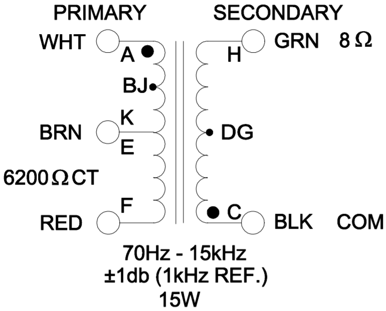
A Class B load line for its 6.2kΩ primary is shown in blue. Full power, assuming no screen current sag, is about 17 watts.
References
1Dave Hunter, Amped, (Minneapolis: Voyageur Press, 2012), p. 73.
2Richard Kuehnel, Guitar Amplifier Electronics: Basic Theory, (Seattle: Amp Books, 2018) pp. 43-50.
3Richard Kuehnel, Guitar Amplifier Electronics: Basic Theory, (Seattle: Amp Books, 2018) p. 18.
4Richard Kuehnel, Guitar Amplifier Electronics: Circuit Simulation, (Seattle: Amp Books, 2019).
5Dave Hunter, Amped, (Minneapolis: Voyageur Press, 2012), p. 73.


