Peavey VTMTM 120 Response Modifications
The Peavey VTM 60 and VTM 120 guitar amplifiers share a common approach to user-controlled circuit modification: dip switches, like this set of 8.
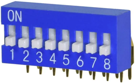
"The most unique aspect of the head are the dip switches. There are eight switches in all, including: two extra stages of gain, compression circuit, two low end modifications, mid range modification and finally two high end modification switches." 1 -Joseph Yankick
This is how Peavey describes amplifier performance with all switches "off."
"This position yields a vintage 'British-style' tube amp response which can be somewhat distorted (depending on Pre/Post Gain adjustment), but it is particularly nice for slightly distorted, punchy, yet distinct guitar sounds." 2
For each of the 8 circuit modification switches, Peavey's owner's manual provides a vivid description of the sonic effects from a guitar player's perspective. We include these descriptions here and then look at the underlying technology based on the published schematic.
Modifications GAIN 1 and GAIN 2
GAIN 1 "Activating this switch adds an additional stage of tube gain and increases the VTM's capacity to overload at low volumes. This additional gain increases the harmonic content of the sound and is an excellent choice for the guitarist looking for a crisp sound with an intermediate amount of distortion which falls between 'vintage' and 'full-tilt crunch'." 2
GAIN 2 "Activating this switch opens the extra tube gain stage all the way to its voltage limits, and, as that statement indicates, maximum all-tube preamp distortion is obtained. This position yields the sound which lucky owners of custom hot-rodded tube amps have had, but owners of stock, out-of-the-box amps have previously heard only on hit records! Tremendous sustain and controllable harmonics at a level many players think impossible are immediately available. Excellent for today's hottest metal stylization." 2
Peavey's switchable boost is implemented by modifying the DC operating point and cathode degeneration3 for the second stage.
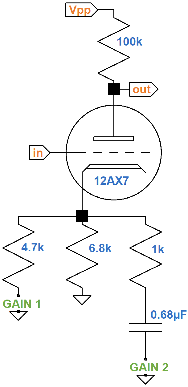
With the GAIN 1 switch open, the 6.8kΩ cathode resistor creates an icy cold bias. With the switch closed, the effective cathode resistor value is created by two resistors in parallel:
RK = 4.7kΩ || 6.8kΩ = 2.8kΩ
This creates a DC grid bias that is a bit cooler than a Fenderish 1.5kΩ but still fairly neutral. 12AX7 operating characteristics show that when the DC grid bias gets warmer the amplification factor μ increases and the plate resistance rp decreases.
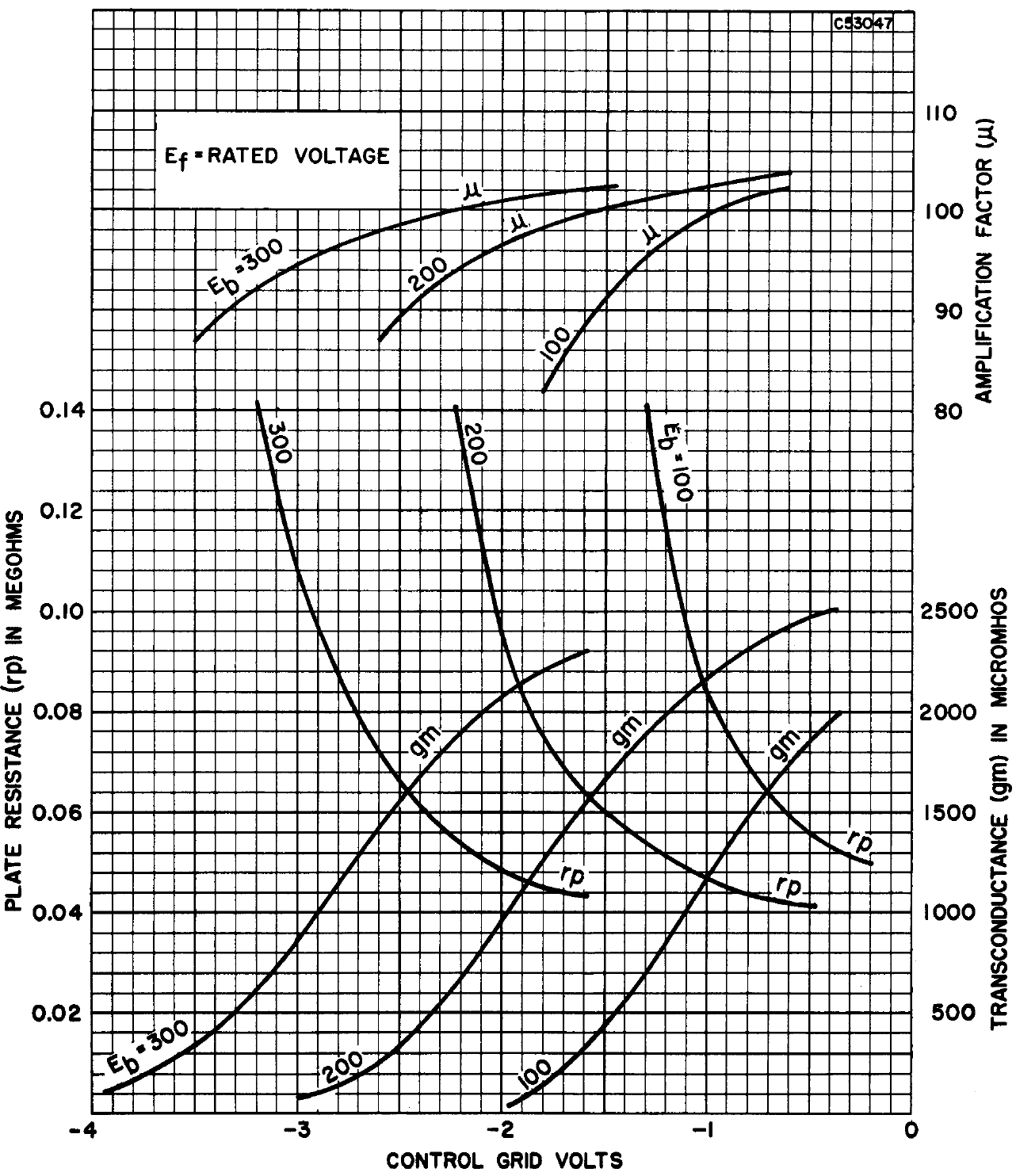
The three sets of curves are for DC plate voltages of 100V, 200V, and 300V. Voltage gain for an unbypassed cathode resistor is4
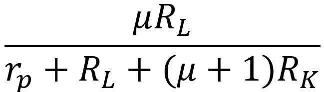
With the entire numerator multiplied by μ, with rp in the denominator, and with RK in the denominator, gain increases when the DC grid bias voltage increases and the cathode resistor value decreases.

|
Guitar Amplifier Electronics: Fender Deluxe - from TV front to narrow panel to brownface to blackface Reverb |
The 0.68μF capacitor blocks DC, so with GAIN 2 closed the DC grid bias does not change. For high-frequency audio signals, on the other hand, the effective cathode resistor value is
RK = 4.7kΩ || 6.8kΩ || 1kΩ = 735Ω
This reduces negative feedback from cathode degeneration, as can be seen from the formula for gain. The transition frequency for a 0.68μF capacitor and a 1kΩ resistor in series is
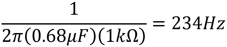
The GAIN 2 switch therefore boosts middle and treble frequencies more than bass. This is an important concern - when the amp is increasingly overdriven, bass can get muddy, saturating midrange with bass-induced harmonics.5

|
Guitar Amplifier Electronics: Basic Theory - master the basics of preamp, power amp, and power supply design. |
Modification COMP
"This switch activates a carefully integrated compressor circuit. (This is one of the major 'secrets' of the elite amp modifiers.) This circuit adds a tremendous amount of 'smoothness' to the sound and further enhances sustain, without sacrificing bite or crunch. This circuit is the key to an incredibly liquid, warm tone that still screams. Full power chords ring clear and fat, single notes sing, and it seems the player only need think 'feedback' and soaring harmonics cut the air like a hail of bullets." 2
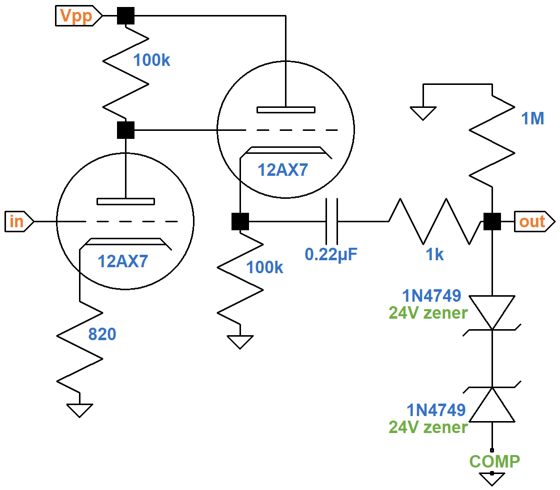
The key ingredient in Peavey's circuit is a pair of 24V zener diodes. These diodes conduct when forward biased, just like normal diode, with a voltage drop of about 0.7V. When reverse biased, no current flows until their design breakdown voltage is reached. For the 1N4749 this is 24V. With back-to-back diodes, no current flows until the voltage across the pair reaches 24.7V, representing the total voltage across one diode in forward bias and one in reverse bias. Both positive and negative swings are clipped at this voltage level when the COMP switch is closed. No current flows through the diodes when the switch is open, so there is no clipping.
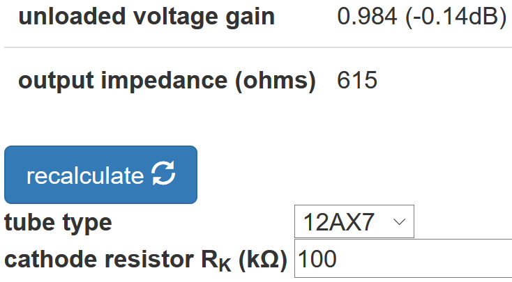
According to the Cathode Follower calculator, the output impedance of the cathode follower is 615Ω.
The 0.22μF capacitor has a reactance of 8.8kΩ at 82Hz that decreases rapidly as the frequency increases. The 1kΩ resistor also has a low resistance, so the three elements in series represent low impedances for the voltage divider they form with the 1MΩ shunt resistor. This creates close to unity gain and a flat response.

|
Fundamentals of Guitar Amplifier System Design - design your amp using a structured, professional methodology. |
Modifications LOW 1 and LOW 2
LOW 1 "This circuit, like the remaining four switched circuits, begins the VTM's ability to contour the overal amp EQ. The Low 1 switch adds a subtle amount of additional low end. It is strictly up to the individual preferences of the user as to the 'correct' amount of bottom end that an amp of this type should have. However, it is to some degree dependent upon the guitar and speaker enclosure used. Properly used, this increased bottom can add punch and fullness to the sound. It must be repeated that this is not a 'tone switch' in the normal sense of the word, but rather a true 'component swap' which is accomplished with a switch." 2
LOW 2 "This circuit, like Low 1, adds additional low end but in a different place than Low 1. (A third low-end voicing is obtained by activating both Low 1 and Low 2.) Again, personal preference will dictate the "proper" low voicing. Please note that even with maximum low end (Low 1 and Low 2 on), muddiness has been scrupulously avoided." 2
These switches add bypass capacitance to the first-stage cathode circuit.
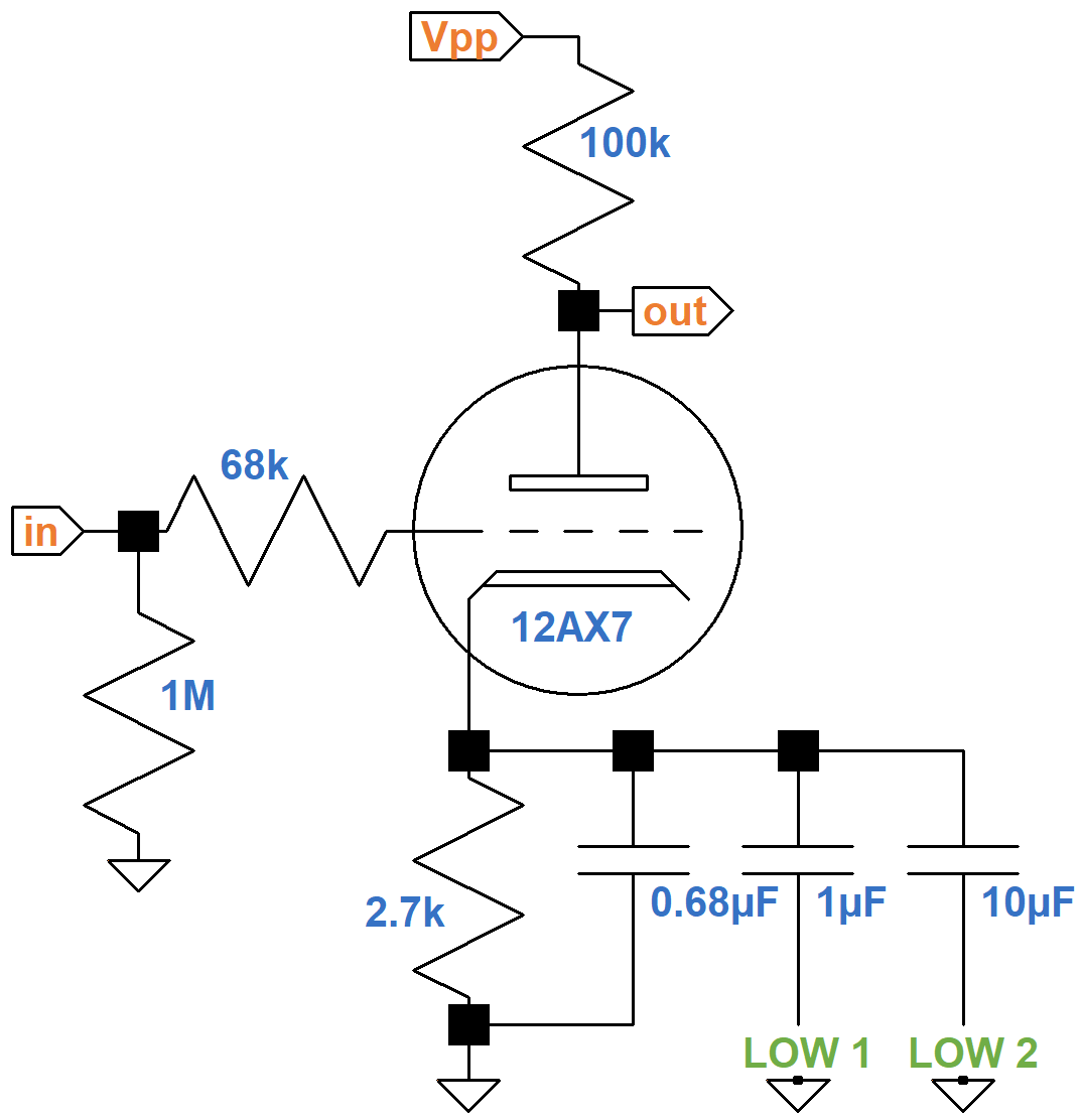
With both switches open, the circuit has 2.7kΩ in parallel with 0.68μF, the same as the bright channel of the Marshall JMP50 Model 1987 "Plexi". This certainly contributes to Peavey's "vintage British-style tube amp response" when all switches are off.
Here is a plot of the frequency response based on SPICE AC analysis.6
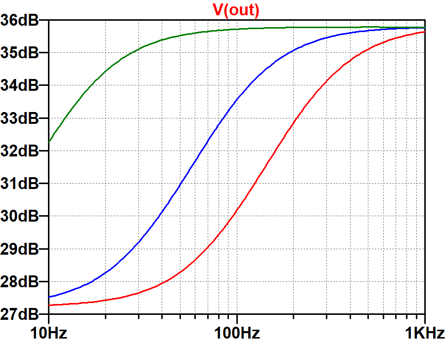
The red, blue, and green traces are for effective cathode capacitor values of 0.68μF, 1.68μF, and 11.68μF, respectively. The red "Plexi" trace shows substantial bright boost. When additional capacitance is switched in, the shape of the transition is the same, but it shifts left to occur at lower frequencies.

|
Guitar Amplifier Electronics: Circuit Simulation - know your design works by measuring performance at every point in the amplifier. |
Modification MID
"This circuit noticeably alters the critical mid-range voicing of the VTM by adding a pronounced mid peak centered in the 'throaty' area. The two mid voicings available from the VTM (Mid On/Off) offer the two major variations most often heard in contemporary music. Mid On is somewhat more 'punchy' and 'percussive'. Mid Off is somewhat more 'cutting' and 'crisp'." 2
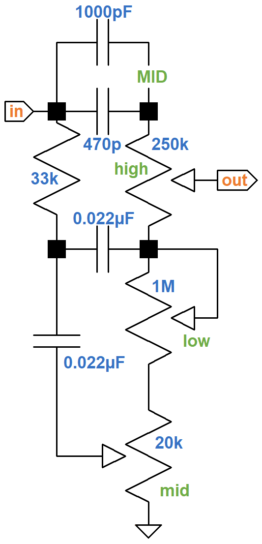
The VTM 60 and VTM 120 use a Fender Bassman style stack. The MID switch adds a 1000pF capacitor in parallel with the 470pF treble bleed for an effective value of 1470pF.
The capacitor value affects middle-frequency scoop and the frequency range under the control of the treble knob. When the capacitance is increased, the middle-frequency range shrinks and scoop decreases, which produces less insertion loss.7
Here is the response with MID switched off and then with it switched on.
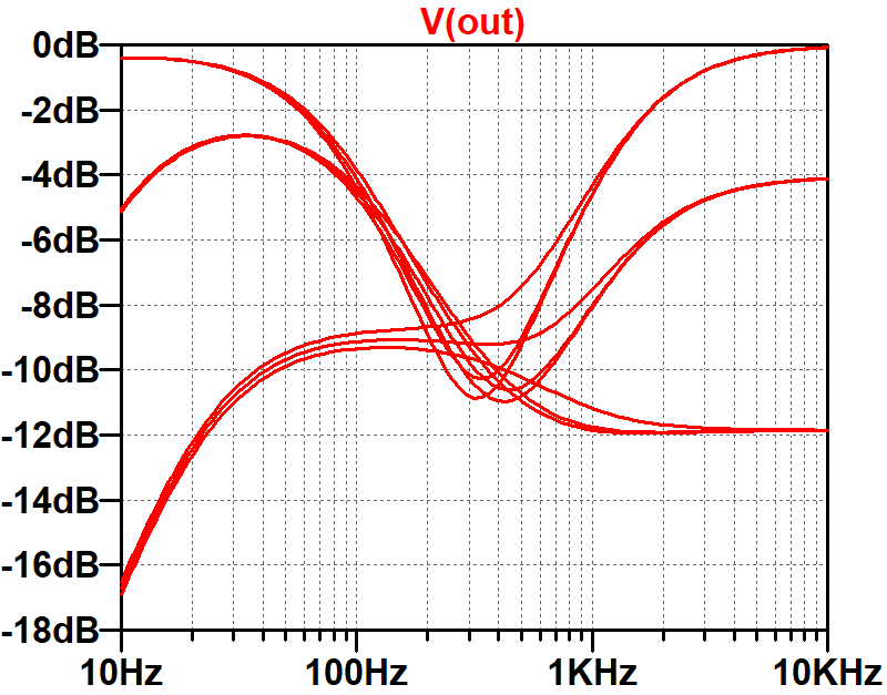
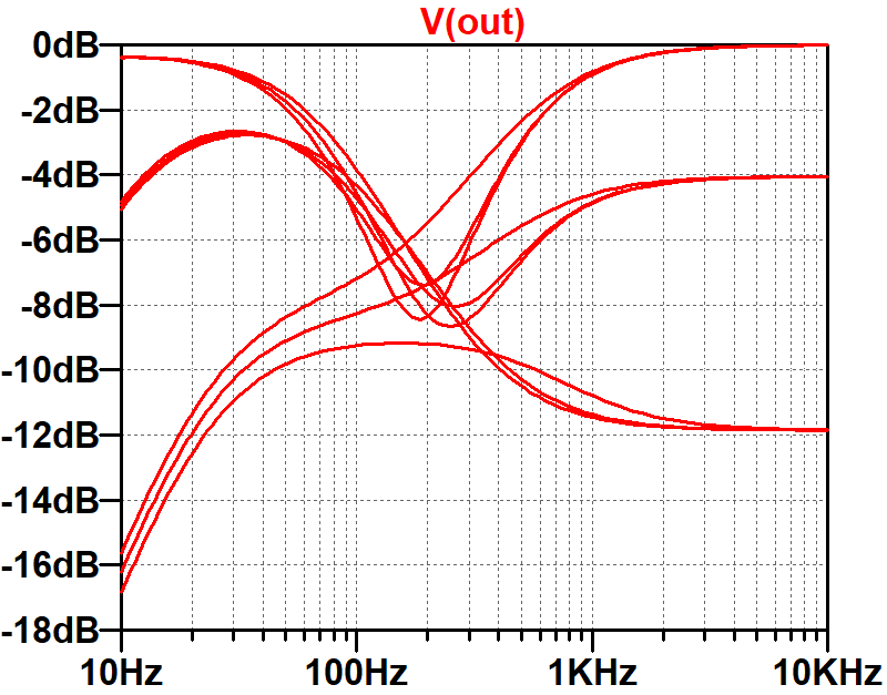
For both simulations, the middle control is at 50-percent rotation. The bass and treble controls are stepped through minimum, 50-percent rotation, and maximum for a total of 9 traces. With the MID switch on, there is about 2dB less scoop and insertion loss. The range of frequencies controlled by the treble control shifts left by about 200Hz.
Modifications HI 1 and HI 2
HI 1 "This circuit alters the high voicing of the VTM, and like all of the EQ 'mods', is a matter of personal preference as to which high EQ is 'correct'. However, it is somewhat dependent upon the guitar and speaker enclosure used. The Hi 1 sounds like it adds 'more' highs, but it actually works by slightly lowering the centering frequency of the active Presence control. This lowers the Presence control from the 'extreme overtones' to the more typical range associated with highs and results in more 'apparent highs'." 8
HI 2 "This circuit (when used in conjunction with Hi 1) further alters the high-end voicing of the VTM. The proper use of the two Hi controls is dependent upon many factors; however, the added 'apparent highs' obtained by activating Hi 1 and Hi 2 are particularly useful in getting a bright sound out of high-output humbucking pickups." 8
These switches are in the long-tailed-pair phase inverter's feedback circuit, which is driven by the 8Ω tap of the output transformer secondary.
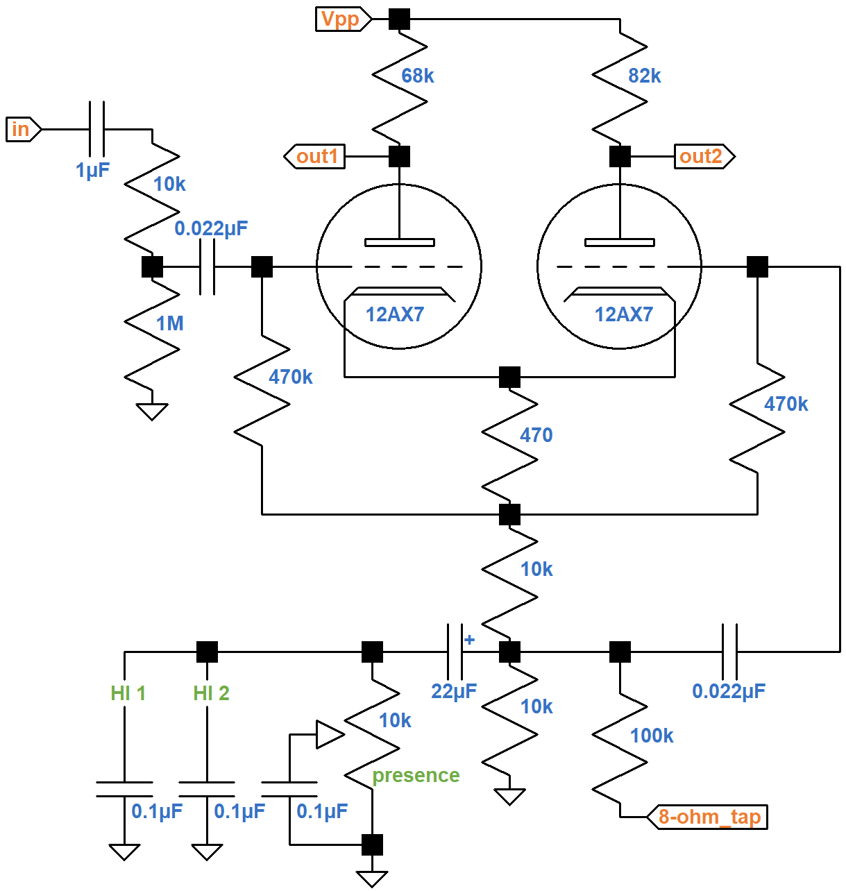
The 0.1μF capacitor connected to the wiper of the presence control shorts high frequencies to ground. With the control cranked up, high frequencies are attenuated in the feedback loop, which boosts high-frequency closed-loop gain.9 For guitar players, the presence knob operates like a bright control. You can crank up the control to continue reining in bass using negative feedback, while allowing treble to run open and free. HI 1 adds a 0.1μF capacitor in parallel for a net value of 0.2μF. HI 2 adds another 0.1μF for a total of 0.3μF.
Here are the results of a SPICE AC analysis simulation measuring the gain from the LTP input to the 8Ω feedback tap with the presence control at maximum.
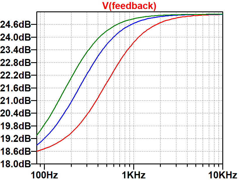
The red trace is with HI 1 and HI 2 off. The blue trace is for HI 1 on and the green trace is for both switches on. With the presence control at minimum, the response is a fairly flat 18.7dB regardless of switch position.
References
1Joseph Yankick, "5 Amp Heads You Should Know About," Noisey, January 14, 2014. Available at https://www.vice.com/en_us/article/6aaej6/5-amps-you-should-know-about (Retrieved June 16, 2020)
2Peavey VTM 60 VTM 120 Owners Manual, p. 2.
3Richard Kuehnel, Guitar Amplifier Electronics: Basic Theory, (Seattle: Amp Books, 2018), pp. 61-65.
4Richard Kuehnel, Guitar Amplifier Electronics: Basic Theory, (Seattle: Amp Books, 2018), p. 77.
5Richard Kuehnel, Fundamentals of Guitar Amplifier System Design, (Seattle: Amp Books, 2019), p. 114.
6Richard Kuehnel, Guitar Amplifier Electronics: Circuit Simulation, (Seattle: Amp Books, 2019).
7Richard Kuehnel, Guitar Amplifier Electronics: Basic Theory, (Seattle: Amp Books, 2018), p. 92.
8Peavey VTM 60 VTM 120 Owners Manual, p. 3.
9Richard Kuehnel, Guitar Amplifier Electronics: Basic Theory, (Seattle: Amp Books, 2018), p. 146.


