TUTORIAL - PENTODE PREAMP DESIGN
Part 2 - DC Operating Conditions
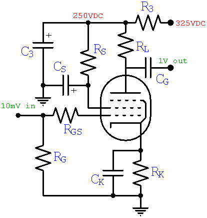
Here is our design so far.
Here are the transfer characteristics for an EF86 pentode, showing plate current versus grid voltage for several different screen voltages:
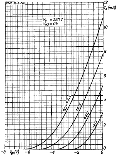
Maximum plate voltage is at cutoff, where the plate current is zero. Minimum plate voltage is at a grid voltage of zero. So the voltage gain of a pentode preamp is roughly these two extremes divided by the grid voltage swing needed to create them. With the plate supply set to 250 volts, the output voltage swings from slightly above zero to 250 volts. For our desired gain of 100, the grid voltage needs a swing of about
250V / 100 = 2.5 volts

|
Guitar Amplifier Electronics: Fender Deluxe - from TV front to narrow panel to brownface to blackface Reverb |
So we want the grid voltage to range from -2.5 volts to zero volts. Here are two possible operating regions that meet this requirement:
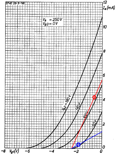
If the EF86 were perfectly linear (We're sure glad it isn't!), the curves would be straight lines. Then we would simply pick the screen voltage "line" that starts at the bottom at a grid voltage of minus 2.5 volts and runs upward to the vertical, zero-grid-voltage line at the right side of the graph. The red and blue lines, for example, represent two possibilities for a perfectly linear pentode. Both lines correspond to a voltage gain of 100 if the plate supply voltage is 250 volts.
We observe that the curve for an imagined 65-volt screen has the same slope as the idealized blue line in the vicinity of the blue circle. Similarly we can imagine a curve for a screen voltage of about 110 volts having the same slope as the red line in the vicinity of the red circle. So these two circles represent possible operating points where the real curves have approximately the same slope as the idealized lines. The blue circle has more gain because it has a lower screen voltage. On the other hand it has less gain because it is near cutoff. These factors cancel to achieve the same overall voltage boost.
|
Guitar Amplifier Electronics: Basic Theory - master the basics of preamp, power amp, and power supply design. |
A DC operating point near the blue circle represents a coldly biased tube with a 65-volt screen operating down in the cutoff weeds, where the curves have a lot more curvature. The red circle is up in the stratosphere of highly linear operation. Both situations limit headroom because they are close to an extreme of possible AC swing.
For maximum headroom let's pick a screen voltage that is approximately halfway between cold and hot bias, VS = 80 volts, as shown here:
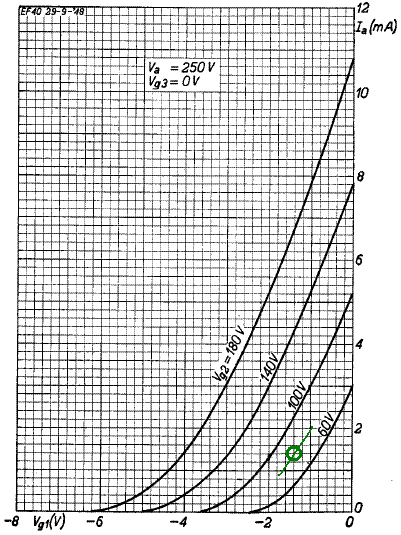
The green circle represents our DC operating point, which is located about halfway between cutoff and zero grid volts along an imagined curve for an 80-volt screen, the center portion of which is approximated by the green line. The DC operating point is defined by the idle screen voltage, grid voltage, and plate current:
VS = 80 volts
VG = -1.4 volts
IPQ = 1.4 milliamps
|
Fundamentals of Guitar Amplifier System Design - design your amp using a structured, professional methodology. |
The transconductance at the operating point, representing the change in plate current versus change in grid voltage, is the slope of the green line. In this case the current changes from 0.8mA to 2mA when the grid voltage changes from minus 1.8 volts to minus 1 volt. So our estimate is
gm = (2mA - 0.8mA) / (1.8V - 1.0V) = 1.5mA/V
This value will come in handy later.
From the triode-connected transfer characteristics, showing the sum of plate plus screen current, we read a current of about 1.6 milliamps at our DC operating point.
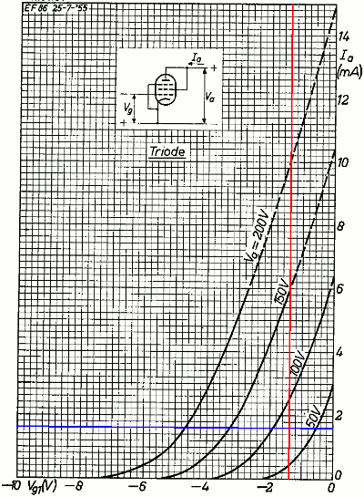
(Notice that the lower curve is for a screen voltage of 50 volts, not 60 volts as in the previous graph.) Our plate voltage won't necessarily be 80 volts, and the graph is only valid when the two electrodes are at the same voltage, but that doesn't matter much. Screen voltage has a much greater influence on plate current than plate voltage.1 Here we see that at a grid voltage of minus 1.4 volts and a screen voltage of 80 volts the total current is about 1.6 milliamps. Since we determined earlier that the idle DC plate current is 1.4 milliamps, the idle screen current is the difference: 0.2 milliamps. (The plate-to-screen current ratio for the EF86 is typically about 6 to 1, so we could have actually skipped this step, but it's nice to rekindle some dormant brain cells every once in a while and actually crunch the numbers.)
|
Guitar Amplifier Electronics: Circuit Simulation - know your design works by measuring performance at every point in the amplifier. |
Resistor Values
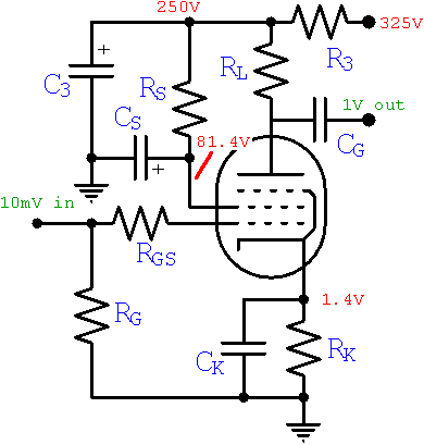
The DC current through the cathode is 1.6 millamps and the desired DC grid voltage is minus 1.4 volts, so according to Ohm's Law the cathode resistor value must be
RK = 1.4V / 1.6mA = 875Ω
We will use the closest standard value: 820Ω. The idle screen current is 0.2mA and the voltage drop across the screen resistor RS is 250V - 81.4V = 169V, so according to Ohm's Law the resistor value is
RS = 169V / 0.2mA = 845kΩ
We will use 820kΩ.
We have been assuming a plate supply voltage of 250 volts throughout our calculations and now we can realize this goal. The total current through power supply filter resistor R3 is 1.6mA, so according to Ohm's Law the resistor value needed to guarantee 250 volts is
R3 = (325V - 250V) / 1.6mA = 47kΩ
Its power rating needs to be at least (325V - 250V)(1.6mA) = 120 milliwatts, so an amp-industry standard half-watt resistor will work fine if it has plenty of air around it.
The voltage gain is the transconductance times the total AC plate load, which is the plate resistor RL in parallel with the 1MΩ volume control at the input to the next stage. We are seeking a voltage gain of 100, so the total plate load needs to be
R = 100 / gm = 100V / (1.5mA/V) = 67kΩ
If we set RL = 82kΩ, then 82kΩ in parallel with 1MΩ gives us 76kΩ. Close enough. If you're getting strong vibes that this seems a bit low for a high-gain voltage amplifier, you're right. Unless the load is an electron-thirsty tone stack or power amp, an EF86 can boost a guitar signal by a factor of 100 in its sleep - try that with a 12AX7!
Wait a minute - time out! Why can't we choose a huge resistor at this point, like a bazillion megohms, and get the gain of a Soldano in a single stage? The reason goes back to our assumption that plate voltage doesn't matter much. If the resistor is very large, then just a few milliamps of plate current drops the plate voltage to near zero. Without a positive voltage at the plate, no amount of screen voltage can coax it into accepting more electrons. Besides, the preamp's output impedance is roughly equal to RL, so even a 1MΩ volume control would start looking like an unbearably heavy load. Now is not time to get greedy with RL. At this point we want merely to fulfill the voltage gain goal that we set out to achieve. Want more? Back up a few steps and reconsider the screen voltage and DC operating point.
According to Ohm's Law the voltage drop across the resistor RL is the DC plate current times the resistor value: (1.4mA)(82kΩ) = 115V. This means the voltage at the plate is 250V - 115V = 135V.
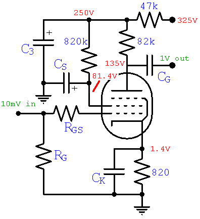
Next we look at AC Characteristics to determine grid circuit and capacitor values.
Reference
1Richard Kuehnel, Guitar Amplifier Electronics: Basic Theory, (Seattle: Amp Books, 2018), pp. 45-47.

|
From system design concepts to individual stage operation, an all-new examination of Bassman electronics. |
