The Current Divider
When two resistors are in series, they each have a voltage based on the current through them. The total voltage is equal to the sum of the individual voltages.
Read that sentence carefully once again. Now check out this cool cut-and-paste:
When two resistors are in parallel, they each conduct current based on the voltage across them. The total current is equal to the sum of the individual currents.
These parallel expressions, pardon the pun, are made possible by Ohm's Law.
Problem
Consider the grid-stopper resistors of the Marshall JCM 800 Model 1992 high-gain input, a design shared by many models of Marshalls and Fenders. What is the equivalent resistance of the two 68kΩ resistors in parallel?
Solution
Let the voltage V across the resistors be 1V. According to Ohm's Law, the current I1 and I2 are then equal to
I1 = I2 = 1V / 68kΩ = 15mA
So there are 0.015C of charge passing through the resistors every second. This means there must be a total of 0.030C per second passing from the input to the output, so I3 = 30mA. The equivalent resistance is one that produces 30mA of current when the voltage across it is 1V. According to Ohm's Law this is
1V / 30mA = 34kΩ

|
Guitar Amplifier Electronics: Fender Deluxe - from TV front to narrow panel to brownface to blackface Reverb |
The JCM 800 high-gain input would thus have the same grid-stopper resistance if we substituted a single 34k resistor for the two 68k resistors in parallel. (Two resistors are needed because they combine differently for the low-gain input. If all we wanted was a high-gain input, then a single 34k resistor would do quite nicely.)
For multiple resistors in parallel the results are similar. If three identical resistors are in parallel, for example, then the equivalent resistance is one third of the value of a single resistor. N equal resistors with values of R in parallel have an equivalent resistance of R / N.
We conclude that the equivalent resistance of two identical resistors in parallel is half the resistance of one of the resistors. This concept is simple and easy to remember. For two unequal resistors in parallel we usually need to pull out a calculator. Fortunately, however, the formula is also simple and easy to remember.

|
Guitar Amplifier Electronics: Basic Theory - master the basics of preamp, power amp, and power supply design. |
Unequal Resistors in Parallel
Things aren't quite so easy when the resistor values are unequal. Let's examine this more general case.
Problem
Consider the parallel grid resistors of the high-gain input of the Ampeg B-22-X, a circuit that is shared by many other Ampegs. What is the equivalent resistance across the 47kΩ and 5.6MΩ resistors in parallel?
Solution
According to Ohm's Law, if we apply 1 volt across the resistors then the currents are
I1 = 1V / 47kΩ = 21.28mA
I2 = 1V / 5.6MΩ = 0.18mA
This means that the total current I3 entering and leaving the circuit is
I3 = I1 + I2 = 21.46mA
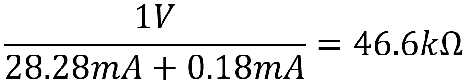
We conclude that when the voltage across the equivalent resistance is 1V, then a total current of 21.46mA is flowing. Applying Ohm's Law, the equivalent resistance must be
1V / 21.46mA = 46.6kΩ
This result is not much different from just the 47kΩ resistor. This is because 5.6MΩ is so much larger than 47kΩ that relatively little current flows through it. The total current I3 is thus completely dominated by what flows through the 47kΩ resistor. We conclude that when the resistor values are vastly different, then the equivalent resistance is approximately the same as the smaller resistor value. What qualifies for being considered "vastly different?" It depends on how accurate you want to be. In general, when one resistor value is 10 or more times greater than the other, then we have crossed the threshold into vastness.

|
Fundamentals of Guitar Amplifier System Design - design your amp using a structured, professional methodology. |
To get a very accurate answer, notice that the total current of 21.46mA is not really of interest. It is merely an intermediate step that we can eliminate by keeping the two individual currents separate:
We then substitute the calculations for the individual current that we completed earlier:
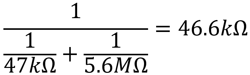
There's obviously a pattern here. For any two resistors R1 and R2 in parallel, we get the equivalent resistance by taking the reciprocal of each of them and adding them together. Then we take the reciprocal of the result.
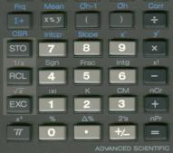 Here is how I actually compute the equivalent value of two parallel resistors. Using my rather ancient Texas Instruments TI-60 calculator, I press 1 divided by the first resistance plus 1 divided by the second resistance. Then I hit the "equals" button and press the 1/x key. (Long gone are the days when I would do this on my sliderule, a classic Keuffel and Esser Decitrig, but every once in a while I'll poke its slide and swing its cursor, just to make sure I still remember how.)
(The image is not the massive Decitrig extracted from its 13-inch leather holster, but the one you see was easier for me to scan.) The formula for the equivalent resistance of resistors in parallel is simple but rather awkward looking because of all of the fractions it contains. We use it often, however, so rather than state it explicitly we often substitute a special symbol instead. It consists of two, appropriately enough, parallel lines. The equivalent resistance of R1 and R2 in parallel is thus denoted by

|
Guitar Amplifier Electronics: Circuit Simulation - know your design works by measuring performance at every point in the amplifier. |
Multiple Resistors in Parallel
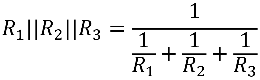
Parallelism can be taken to extremes. The equivalent resistance of three parallel resistors, for example, is
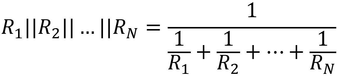
The equivalent for N resistors of value R in parallel is
This may seem needlessly academic. After all there aren't many guitar amp schematics with N identical resistors in parallel. But let's think outside the chassis. Here's a practical example. Let's say we want to construct an 4-ohm dummy load for our test bench and we want it to handle 50 watts. A single 50-watt resistor is a rather large beast. As an alternative we could use five 20-ohm resistors in parallel. Voila - the equivalent resistance is 4 ohms and each resistor only needs to handle 10 watts. (This assumes the resistors are sufficiently separated from each other for adequate cooling and that your test bench isn't located in Thailand in April or May.)
The Current Divider
Our previous examination of resistors in series led to the concept of a voltage divider. It stands to reason that our examination of resistors in parallel leads to the concept of a current divider.
Problem
For the same Ampeg B-22-X circuit, what is the current I2 compared to the total current I3?
Solution
By combining all that we learned from the previous problem it is easy to show that
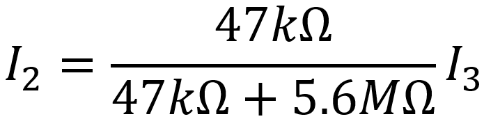
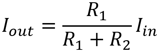
In general, when a total current Iin is applied across two resistors R1 and R2 in parallel, the output current through R2 is