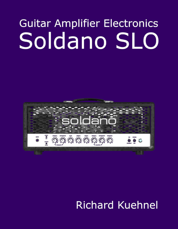
Circuit Analysis of the Soldano Super Lead Overdrive Channel
"Word of the SLO spread quickly, and early adopters included luminaries like Toto guitarist and session ace Steve Lukather, Lou Reed, Eric Clapton and, perhaps more crucial to the SLO's enduring legacy, a cohort of heavy metal shredders like Dokken's George Lynch, Ratt's Warren DeMartini, and Steve Vai." 1
The SLO offers creamy overdrive at any volume level, with a compression and sustain-for-days harmonic tonality that preserves the articulation of each pick attack.
"Simple tonal descriptions are more apt, and players tend to be drawn to the big, thick, creamy drive, which can also be plenty nasty and aggressive as desired, while retaining musical highs and firm, chunky lows." -Dave Hunter2
The preamp's cascading-gain architecture requires several triodes to implement, but each is dedicated to a pivotal role in the signal chain. With only two channels and a simple switching mechanism, the SLO has a surprisingly compact architecture for creating such a rich palette of tones.
"It's easy to get caught up in much of the technology features, buzzwords and extras that today's amps can offer. Extra channels, lots of buttons and footswitch control with MIDI and onboard digital signal processing, etc. But if your interests are in capturing great vacuum tube tone with a surprising range of tonal control and gain versatility, the pure circuit and quality build and components used in the Soldano SLO just might be the amp that can feel liberating to play through. Sometimes less really can be more." -David Szabados3
In 1987 Mike Soldano guillotines the traditional single-triode preamp. Instead, he offers gobs of gain crafted in a way to avoid the fizz, boost the sustain, and serve up creamy saturation to a relatively high-fidelity power stage. The SLO preamp, the electronics upstream of the effects send jack, is the star of Soldano's show. It represents a stunning achievement that marks this amp's place in history.
The SLO has two channels with a shared first stage. The analysis here concerns the high-gain channel, in which the signal passes through four stages of voltage amplification prior to a DC-coupled cathode follower that drives the effects send.
First Stage 12AX7 Preamp
The first and second stages are common cathode voltage amplifiers with partially bypassed cathode resistors. They are coupled by a voltage divider formed by a 470kΩ resistor and 500kΩ gain control. The 2000pF capacitor allows treble frequencies to bleed past the voltage divider's attenuation.

Some versions add a 1000pF bright boost capacitor at the top of the gain control, as shown here. Its purpose is to compensate for human perception of treble cut at lower volume settings. In this circuit, that perception is enhanced because the top of the potentiometer adds series resistance to increase treble attenuation caused by Miller capacitance at the grid of the second-stage triode.

|
New! Guitar Amplifier Electronics: Fender Deluxe - from TV front to narrow panel to brownface to blackface Reverb |
The guitar input jack connects to a classic gamma network comprised of a 1MΩ grid leak resistor and a 68kΩ grid-stopper resistor. Across this network there is unity (0dB) midrange gain and very little treble attenuation due to Miller capacitance. The purpose of the grid-stopper resistor is to attenuate only radio frequencies.
According to the 12AX7 calculator, for a plate supply voltage of 360V, a 220kΩ plate load resistor, and a 1.8kΩ cathode resistor, the DC grid bias is -1.5V.


The calculator shows a DC plate-to-cathode voltage of 176V and a DC current load on the power supply of 0.83mA. The green AC load line is based on the 970kΩ effective AC load established by the 470kΩ series resistor and 500kΩ gain control. It indicates that the grid voltage can swing from 0V to -4V, so the bias is warm and input headroom is 1.5V peak (+0.5dBV) for fully bypassed frequencies, well beyond the output capability of a single-coil pickup. It is greater at 82Hz. Without external boost, this stage runs clean.
|
Guitar Amplifier Electronics: Basic Theory - master the basics of preamp, power amp, and power supply design. |
Let's assume the gain control is at maximum, so the 1000pF bright bypass capacitor, if present, is shorted. The 0.002μF bypass capacitor has a reactance that matches the resistance of the 470kΩ resistor at a frequency of 169Hz. This represents the transition point for high-frequency bypass. The Cathode Bypass Capacitor calculator shows loaded gain versus frequency measured at the plate if the capacitor is not in the circuit, which is essentially true for bass. Clearly the cathode resistor is only partially bypassed - there is 3.2dB bass attenuation compared to treble.

The 0.002μF bypass capacitor is almost an open circuit at 82Hz, so the loaded gain for the lower limit of bass is represented by the calculator value of 34.2dB.
The calculator's value of 37.4dB would be the gain at 10kHz were it not for the 0.002μF capacitor. At high frequencies the capacitor is a short circuit, so the circuit at 10kHz is essentially a triode voltage amplifier with a 220kΩ plate load resistor, a fully bypassed 1.8kΩ cathode resistor, and a 500kΩ AC load. The Preamp Gain and Output Impedance calculator shows that under these conditions the unloaded (midrange and treble) gain and output impedance are 37.8dB and 49kΩ, respectively.

The 49kΩ output impedance forms a voltage divider with the 500kΩ control for a voltage "gain" of 500kΩ / (500kΩ + 49kΩ) = 0.91 (-0.8dB). High-frequency gain is therefore 37dB. We can conclude that loaded gain measured at the plate is 34.2dB at 82Hz, increasing to 37dB at 10kHz. The output impedance at high frequencies is 49kΩ. At low frequencies it is a bit more, but the value is completely dominated by the 470kΩ series resistor.
|
Fundamentals of Guitar Amplifier System Design - design your amp using a structured, professional methodology. |
The Coupling Capacitor calculator shows that 0.02μF provides an adequate bass response.

Gain at 82Hz is down by less than a tenth of a dB, so for guitar signals the capacitor is a short circuit. Gain at 10Hz, well below audio, is down by 2dB, which contributes to inter-stage plate supply decoupling.
At 82Hz, the voltage divider formed by the 470kΩ series resistor and the 500kΩ control introduces a voltage "gain" of 500kΩ / (500kΩ + 470kΩ) = 0.52 (-5.6dB). The gain from guitar input jack to the top of the control is therefore 34.2dB - 5.6dB = 28.6dB. At 10kHz, the series resistor is shorted, so there is no attenuation. The voltage gain measured at the top of the control is the same as at the plate: 37dB.
At high frequencies, the second stage has an unloaded voltage gain of 61.5. Because it drives a very high-impedance load, the loaded voltage gain is about the same. According to the Grid Stopper Resistor calculator, the 470kΩ series resistance at its grid creates substantial treble attenuation.

The calculator shows 11.3dB attenuation at 10kHz. The gain measured from grid-to-grid is therefore 37dB - 11.3dB = 25.7dB.
|
Guitar Amplifier Electronics: Circuit Simulation - know your design works by measuring performance at every point in the amplifier. |
The net result of the first stage and the coupling to the second stage is substantial voltage gain with an emphasis on midrange. The following graph, in dB versus hertz, depicts gain from grid to plate, grid to the top of the gain control, and grid to grid.

This SPICE simulation4 assumes the gain control is at maximum. It also assumes that the triode has an amplification factor of 100 and a plate resistance of 62.5kΩ, which is close to reality for an average tube at a DC plate current of 0.83mA. Midrange grid-to-grid gain is about 36dB.
Second Stage 12AX7 Preamp
The second stage connects to an attenuator and the third stage, which has an unbypassed cathode resistor and a plate bypass capacitor.

According to the 12AX7 calculator, for a plate supply voltage of 350V, a 100kΩ plate load resistor, and a 1.8kΩ cathode resistor, the DC grid bias is approximately -2V.


The actual AC load is 1.47MΩ, which is very light, so the AC load line almost coincides with the DC load line. To better mark the DC operating point, I have set the AC load to an arbitrary low value of 123kΩ.
The calculator shows a DC plate-to-cathode voltage of 240V and a DC current load on the power supply of 1.1mA. Following the red "AC" load line, the grid voltage can swing from 0V to -4.5V, so the bias is fairly neutral and input headroom is 2V peak (+3dBV) for fully bypassed frequencies.
The same 0.02μF coupling capacitor value is used here. A repeat of the procedure used for the first stage reveals that it creates negligible bass attenuation.
Unlike the first stage, this triode has a 100kΩ plate load resistor. Parts values at the cathode, however, are identical to the first stage. The Cathode Bypass Capacitor calculator shows that the second stage cathode resistor is also partially bypassed - there is 4.7dB bass attenuation compared to treble, representing slightly more bass cut than for the first stage.

These gains represent the loaded gain measured at the plate, accounting for the voltage amplifier's output impedance and the AC load.
Coupling between stages is via a voltage divider formed by the 470kΩ series resistor and the 1MΩ grid leak. Coupling "gain" is 1MΩ/(1MΩ+470kΩ) = 0.68 (-3.3dB).
At high frequencies, the gain of the third stage is substantially reduced by a plate bypass capacitor. Moreover, overall gain is severely reduced by an unusually large (39kΩ) unbypassed cathode resistor. These factors combine to all but eliminate treble attenuation caused by the Miller effect.
The net result is about 30.8dB - 3.3dB = 27.5dB gain at 82Hz, 35.6dB - 3.3dB = 32.3dB gain at 10kHz, and almost 32.3dB at midrange, creating an overall voltage boost with bass cut. The following graph, in dB versus hertz, shows the gain from grid to plate and grid to grid.

Midrange grid-to-grid gain is approximately 32dB.
Third Stage 12AX7 Preamp
The third stage of the high gain channel connects to the normal channel via a high impedance, which can be ignored, leaving only a simple gamma network formed by a 330kΩ grid leak and a 220kΩ grid stopper connecting it to the fourth stage.

According to the 12AX7 calculator, for a plate supply voltage of 350V, a 100kΩ plate load resistor, and a whopping 39kΩ cathode resistor, the DC grid bias is an icy cold -4V.


The AC load is 330kΩ. The calculator shows a DC plate-to-cathode voltage of 336V and a DC current load on the power supply that is minuscule: 0.1mA. The green AC load line shows the maximum extent of guitar signal swing inside the 12AX7 vacuum tube. It indicates that the triode's grid-to-cathode voltage can swing between 0V and -4.3V. Input headroom for the voltage amplifier stage, however, is relative to ground, not the cathode. The extent of grid-to-ground voltage swing is hugely impacted by the negative feedback caused by the unbypassed cathode resistor, which is unusually large. For the grid-to-cathode voltage to swing from -4V to a cutoff value of -4.3V, the grid-to-ground voltage needs to swing by 0.3V plus (39kΩ)(0.1mA) = 3.9V for a total of 4.2V. Input headroom is therefore 4.2V peak (+9.5dBV). This is considerably greater than for the first two stages, despite a DC operating point very close to cutoff.
The Preamp Gain and Output Impedance calculator shows that the unloaded gain is only 7.7dB because of the tremendous amount of negative feedback introduced by the large, unbypassed cathode resistor.

(The calculator assumes the tube is operating under normal conditions. Here the tube is operating at a plate current of only 0.1mA, which is extremely low. This means the amplification factor is lower and the plate resistance is higher than generally assumed. The data sheet provides parametric data down to 0.2mA plate current, from which we can stretch our imaginations and estimate that the unloaded gain for 0.1mA is somewhere in the neighborhood of 7dB.) The output impedance is more than double a fully bypassed situation: 98kΩ. (This matches the actual value despite low DC plate current.) Both calculations neglect the effects of the plate bypass capacitor.
The voltage "gain" of the voltage divider formed by the output impedance and the 330kΩ grid leak is 330kΩ / (330kΩ + 98kΩ) = 0.77 (-2.3dB). The loaded gain is thus 7.7dB - 2.3dB = 5.4dB.
The Plate Bypass Capacitor calculator shows that this gain holds for bass when the bypass capacitor acts as an open circuit. At about 1kHz, attenuation from the 1000pF capacitor begins to kick in. By 10kHz, loaded gain is deep into negative territory: -8.4dB.

The Preamp Gain and Output Impedance calculator shows that the fourth stage has an unloaded, high-frequency voltage gain of 78, which also represents its loaded gain because it drives a light AC load.

The reactance of the plate bypass capacitor matches the 100kΩ plate load resistor value at 1 / [2π(1000pF)(100kΩ)] = 1.6kHz, so at low treble frequencies the output impedance is transitioning from high to low. At 10kHz it is quite low. According to the Grid Stopper Resistor calculator, an output impedance of zero produces 6.6dB attenuation at 10kHz. This is close to the actual value.

The net effect is a gain of 5.4dB at 82Hz with increasing attenuation starting at midrange. At 10kHz net gain from the grid of the third stage to the grid of the fourth stage is -8.4dB - 6.6dB = -15dB. The following graph, in dB versus hertz, shows the gain from grid to plate, grid to the top of the grid-leak resistor, and grid to grid.

Midrange grid-to-grid gain is approximately 5dB.
Fourth Stage 12AX7 Preamp and Cathode Follower
The fourth stage drives a cathode follower that drives the SLO's effects send.

The fourth stage is configured the same as the first but with just a slightly higher plate supply voltage, so it has approximately the same DC operating point: a DC plate-to-cathode voltage of 176V and a cathode-to-ground voltage of 1.5V. This means its plate-to-ground voltage is 177.5V, which sets the DC conditions for the cathode follower that it drives. The DC current load on the power supply is 0.8mA plus the load of the cathode follower, which is about 1.8mA. Input headroom for fully bypassed frequencies is also the same as for the first stage: 1.5V peak (+0.5dBV).
The Cathode Bypass Capacitor calculator indicates that midrange gain is about the same as at 10kHz: 37.8dB.

Midrange gain, from the grid of the voltage amplifier to the grid of the cathode follower, is therefore 37.8dB.
According to the Cathode Follower calculator, the voltage gain for the DC-coupled cathode follower is near unity (-0.1dB) and the output impedance is a very low 615Ω.

The output impedance and 100kΩ resistor form a series resistance that combines with a 1kΩ shunt resistance to form a voltage divider to attenuate the signal level for the effects send. 100kΩ is so much larger than the cathode follower output impedance that the latter is hardly worth mentioning. The voltage "gain" of the voltage divider is 1kΩ / (1kΩ + 100kΩ) = 0.0099 (-40.1dB).
Fifth Stage 12AX7 Effects Recovery
The fifth stage voltage amplifier, which also drives a cathode follower, uses a larger cathode resistor that is fully bypassed.

The cathode follower provides a low output impedance capable of driving the Soldano's Bassman-style tone stack, which demands a lot of current.
According to the 12AX7 calculator, for a plate supply voltage of 378V, a 220kΩ plate load resistor, and a 2.2kΩ cathode resistor, the DC grid bias is -1.75V.


The actual AC load is very light, so the AC load line matches the DC load line. I set the AC load to an arbitrary low value of 123kΩ to better mark the DC operating point.
The calculator shows a DC plate-to-cathode voltage of 200V and a DC current load on the power supply of 0.8mA plus the DC plate current of the cathode follower, which is about 2mA. Following the red "AC" load line, the grid voltage can swing from 0V to -4.5V, so the bias is fairly neutral. Input headroom is therefore 1.75V peak (+1.9dBV).
Overdrive and Input Sensitivity
The fifth stage is the final voltage amplification stage prior to the master volume control and it has an input headroom of +1.9dBV. The attenuator for the effects send has a "gain" of -40.1dB; the cathode follower upstream of the attenuator has approximately unity gain; and the fourth stage voltage amplifier has a gain of 37.8dB. To overdrive the fifth stage, the input to the fourth stage needs to be +1.9dBV + 40.1dB - 37.8dB = +4.2dBV. Fourth stage input headroom is only +0.5dB, however, so the fourth stage breaks into overdrive well before the fifth. This is an important design feature: the fifth stage remains within its headroom limits, even under severe preamp overdrive conditions. The fourth stage, which is strategically upstream of the effects loop, produces overdrive distortion that is within the headroom limits of the fifth stage.
Placing an effect like reverb downstream of distortion produces reverberated distortion instead of distorted reverberation. With the master volume control dialed down, the effects return, phase inverter, and power amp should run clean, restricting distortion to the upstream preamp.
For a classic, circa 1960 guitar amplifier, input sensitivity is the signal amplitude at the amplifier's input jack needed to drive the power amp to full power. (It could be said that failure to provide sufficient voltage amplification to drive the power amp to full power is perhaps the ultimate embarrassment for an amp builder!) For a high-gain amplifier, the definition of input sensitivity can be updated to include the minimum signal level capable of driving the preamp distortion stage into overdrive.5 For the Soldano design, the distortion stage is the fourth and it requires +0.5dBV (1.5V peak) to reach its input headroom limit. Let's see what the guitar needs to produce to reach this level.
By design, the SLO high-gain channel has considerable bass and treble cut. Here are the gains at midrange between the input jack and the fourth stage input with the gain control set to 50-percent rotation (10-percent resistance for an audio taper).
| 1st stage: | 36dB |
| gain control: | -20dB |
| 2nd stage: | 32dB |
| 3rd stage: | 5dB |
Working backwards from the required signal level to overdrive the fourth stage, the signal
level required at the guitar input jack, representing input sensitivity, is
+0.5dBV - 5dB - 32dB + 20dB - 36dB = -52.5dBV (3.4mV peak). Whoa Nelly! This is almost an order of magnitude greater than for a classic (before preamp overdrive) guitar amp. When the gain control is cranked up to maximum, input sensitivity is only -72.5dBV (340μV peak).
When the signal level at the input to the fourth stage is +0.5dBV, i.e. right on the verge of overdrive, the signal level at the effects send is +0.5dBV + 37.8dB - 40.1dB = -1.8dBV (1.2V peak). In overdrive, the stage is at its limits of output voltage swing, so this represents an upper limit for the signal level to the pedal.
Key Features of the Soldano Design
Following the fifth stage cathode follower is the tone stack and master volume control. The controls work together to attenuate the preamp output, thereby providing frequency-selective control over post-distortion harmonics. If the tone stack were located further upstream and separated from the overdrive control by one or two stages of voltage gain, the results would be quite different.
Soldano's tone stack and overdrive control, with plenty of insertion loss, are placed between the last preamp stage and the phase inverter, so the phase inverter always has enough headroom to drive the power amp to full power and beyond. Except in extreme cases, overdrive is limited to the preamp or the power amp, not the phase inverter.
Soldano's effects loop follows the fourth stage, which is the first preamp stage to break into overdrive. This ensures that distortion harmonics are upstream of the loop. Effects thus operate on the distorted signal, not the input to the distortion-producing stage. In the case of reverb, for example, the preamp creates reverberated distortion, not distorted reverberation.
Three of Soldano's voltage amplifiers use relatively small cathode bypass capacitors. Partial bypassing creates negative feedback for low frequencies, thereby creating bass attenuation. Attenuating bass via feedback, rather than coupling, is a trait throughout this design.
Soldano's third stage includes a plate resistor bypass capacitor with a transition frequency in the low treble range. Any treble from the guitar pickups that manages to run the gauntlet of the upstream grid stopper suffers a substantial cut. The nature of overdrive, however, is harmonic distortion, and this amp creates bucket loads of its own high-frequency content. Soldano's design introduces harmonic distortion generated predominantly by the guitar's fundamental frequencies. High frequency content is created by overdriving the amplifier.
Solo guitar voice usually has a range of only 2 or 3 octaves. Limiting the passband reduces intermodulation distortion and a plethora of extraneous and undesirable harmonic artifacts that can pollute the mix.
In traditional designs, the power amp is the first stage in the signal chain to break into extreme distortion. Except under unusual circumstances it is the only stage to succumb to bias excursion, which contributes substantially to the distortion dynamics of Class AB. Without proper foresight, however, bias excursion can lead to highly undesirable effects like blocking distortion. By incorporating a 4-knob master volume control, Soldano creates the opportunity to overdrive the preamp while allowing the power amp to run relatively clean. This shifts the potential for bias excursion to the overdriven preamp stage. To prevent blocking distortion, Soldano uses grid stoppers to ensure that the overdriven stage's input impedance remains high even under grid current conditions. Only the first stage and the effects return, which are unlikely to be overdriven, have an input impedance of less than 220kΩ.
From the perspective of the grid to which the grid stopper is attached, the resistor adds substantially to the output impedance of the upstream stage. The high output impedance is incapable of providing the current necessary to drive the grid positive by any appreciable amount. This makes the driven tube's transition from near linear operation to severe distortion relatively sharp. Large grid stoppers also have a substantial impact on treble response, but in the context of the higher-order harmonics created by overdrive, there is plenty of brightness in the final result.
The first triode to break into overdrive is the directly coupled cathode follower in the fourth stage. Overdriving the cathode follower in the positive direction causes a drop in the plate-to-cathode voltage, making electrons more attractive to the grid. The resulting increase in grid current causes more current to flow through the driving triode's plate load resistor, thus limiting the decreasing voltage across it. As the driving triode approaches cutoff, the cathode follower's input impedance drops from an extremely high value, representing a very light load, to a very low value that loads down the driving circuit. This sharpens the clipping of the signal and makes it a more symmetrical match to clipping in the opposite direction. As Rutt observes, there is no equivalent to this phenomenon in transistor circuits.6
Wires and components have inherent inductance and capacitance that can lead to parasitic oscillation. This highly undesirable affect, which often occurs at radio frequencies, is caused by feedback from output circuits to input circuits. High-gain preamps are particularly susceptible. Soldano's generous use of grid stopper resistors helps attenuate the outbreak of parasitic oscillation. The SLO's plate bypass capacitor in the third stage also chokes off high frequency signals, effectively isolating upstream stages from downstream stages for the span of frequencies over which oscillation can occur. It is worth emphasizing, however, that grid stoppers, plate bypass capacitors, and other proactive measures are effective only in the context of good circuit layout. Parts and wire placement are crucial in a high-gain preamp.
High gain works for both signals and noise. At the input jack, Soldano uses a classic gamma network with a 68k grid stopper and 1M grid resistor. This allows all guitar signals to pass to the first tube unattenuated. Attenuation and frequency shaping take place only after the signal is strong enough to compete with the noise generated by downstream circuits.
References
1Tom Beaujour, "Soldano Super Lead Overdrive 30 Review," Guitar Player, April 2021.
2Dave Hunter, "The Soldano Super Lead Overdrive," Vintage Guitar, July 2011.
3David Szabados, "The Legend of the Soldano Super Lead Overdrive," Legendary Tones, April 11, 2016.
4Richard Kuehnel, Guitar Amplifier Electronics: Circuit Simulation, (Seattle: Amp Books, 2019).
5Richard Kuehnel, Fundamentals of Guitar Amplifier System Design, (Seattle: Amp Books, 2019), pp. 44-46.
6T.E. Rutt, "Vacuum Tube Triode Nonlinearity as Part of The Electric Guitar Sound," 76th Convention of the Audio Engineering Society, New York, 1984.
7Richard Kuehnel, Guitar Amplifier Electronics: Basic Theory, (Seattle: Amp Books, 2018).
