The Marshall JCM800 Model 2204 Power Amp
"The lead mode is what most players sought out these new Marshalls for, and that extra half a triode made one hot rock amp." 1 -Dave Hunter
The JCM800 power amp follows a long lineage of classic amplifiers that include the Fender Bassman 5F6-A, the Marshall JTM45, the Model 1962 "Bluesbreaker," and the Model 1987 "Plexi." It has substantially more power supply filtering than any of its ancestors, which contributes to a slower, more sustained dynamic as the amp is overdriven. We'll examine the effects here. The amp also derives negative feedback from the 4Ω output transformer tap instead of the Plexi's 8Ω tap and doubles the feedback resistor connecting it to the phase inverter. We'll look at these artifacts as well.
DC Operating Conditions
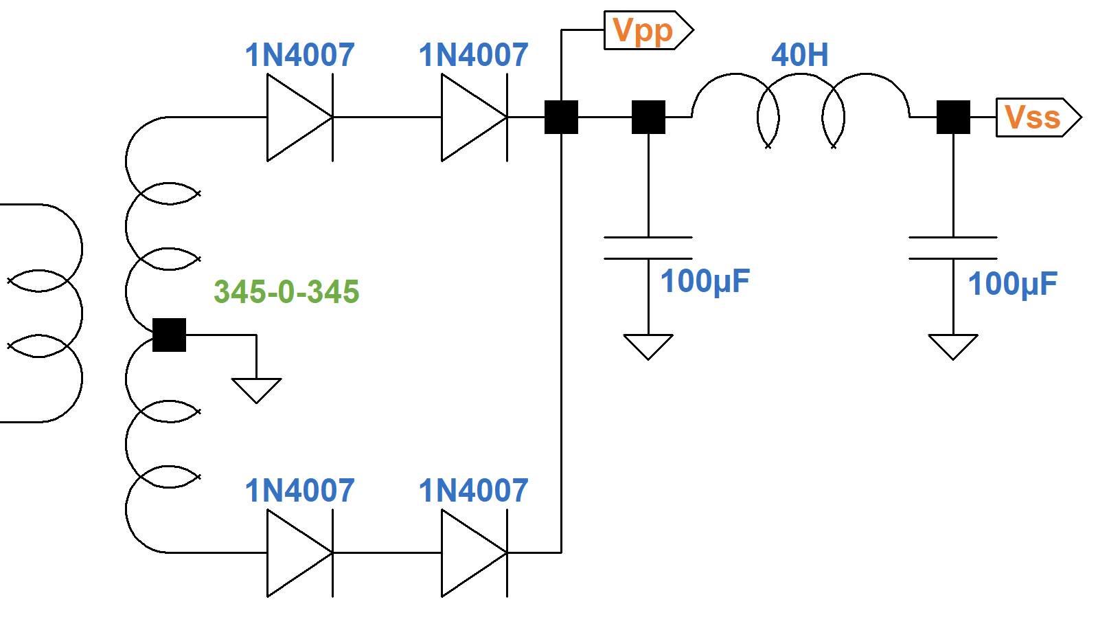
Here is the power amp and power supply. The voltages are calculated values, not measured values, as described below.
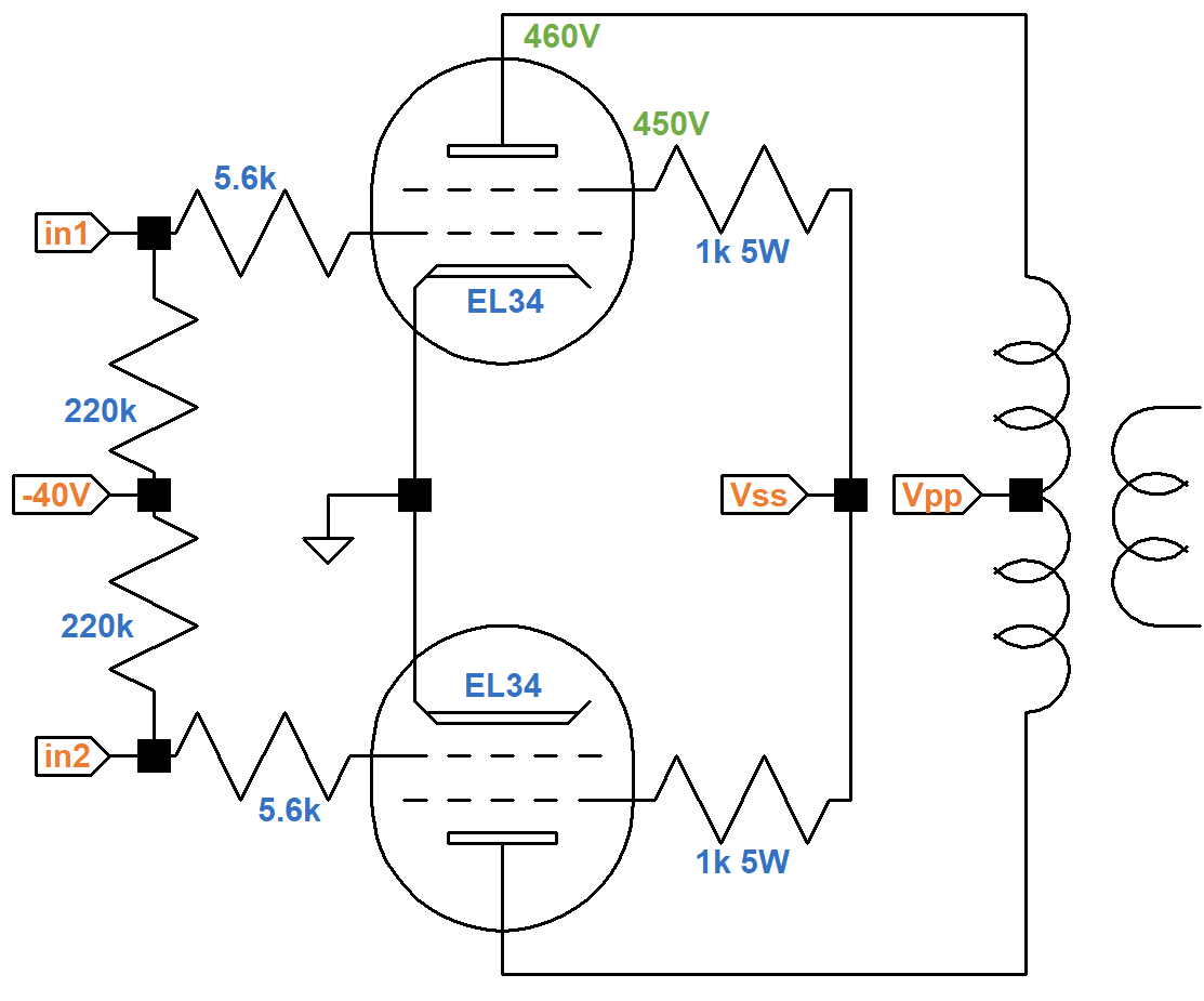
The 345-0-345 volt RMS power transformer creates 488VDC if there is no load or rectifier loss.
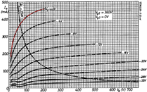
If we assume 5-percent sag and less than 5VDC loss across the output transformer primary, then we get about 460V at the EL34 plates. (For Class AB and a solid state rectifier there is little sag at idle.) A drop of less than 5V across the choke gives us at least 455V at the top of the 1k Screen resistors. Let's assume about 5mA screen current and see if this holds up under additional scrutiny. That creates a 5V drop across the screen resistors to put 450V at the screens. The blue curve shown here on the transfer characteristics is our estimate for a 450V screen.
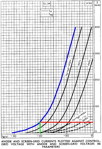
Maximum plate dissipation for the EL34 is 25 watts, so if we bias the amp at 70 percent, we get 18 watts, making the idle plate current 18W / 450V = 40mA. This is the red line which intersects the curve at a grid voltage of minus 40V. By examining the transfer characteristics for screen current at the bottom of the graph, we observe that the idle screen current is well under 10mA, well within the plus-or-minus 20 percent standard of tube amp design, so our original estimate for screen voltage appears reasonable.

|
Guitar Amplifier Electronics: Fender Deluxe - from TV front to narrow panel to brownface to blackface Reverb |
Power Supply Dynamics
According to the LC Ripple Filter Calculator there is 64dB of ripple attenuation for 50Hz AC across the 40H choke. For 60-Hertz power it is 67dB. This is substantially more than earlier Marshalls. The JTM45, Bluesbreaker, and Plexi have 20H chokes. The Bassman uses only 10H. Filter capacitor values also increased through the lineage as the price of high-voltage electrolytics dropped. The JTM45 has 32μF on each side of the choke. The JCM800 uses 100μF. The direct result is substantially less hum in the plate and screen supplies. What is sometimes overlooked, however, is the effect of these changes on the dynamics of the power stage when the amp is overdriven.
The resistances in the power transformer, the internal plate resistance of the rectifier tube, and the resistance in the choke cause the DC voltage supplying the power amp screens to sag exponentially. The choke and filter capacitors also interact with one another to cause the voltage to oscillate somewhat, as shown in the following figure.2 The graph shows power supply voltage sag in the Fender Bassman 5F6-A over the first 500 milliseconds after the onset of a full-power signal.
The red, solid curve is the actual sag. The blue, dotted curve shows the first order component, whose drop in voltage is determined by the increase in current demand and the characteristics of the power transformer and rectifier. The time period over which the sag takes place depends mostly on the size of the choke and filter capacitors. The JCM800's larger filter reacts more slowly. The black, dashed curve shows the second-order transient, which is caused by the interaction of the choke with the capacitors on either side. This transient is more prominent and decays less quickly in the JCM800.

|
Guitar Amplifier Electronics: Basic Theory - master the basics of preamp, power amp, and power supply design. |
Negative Feedback
The JCM800 derives negative feedback from the 4Ω output transformer tap instead of the Model 1987's 8Ω tap. It also increases the value of the feedback resistor connecting it to the phase inverter: from 47kΩ to 100kΩ. Both factors combine to lower negative feedback by a factor of three.3
Overdriving the power amp causes output clipping and clamping, which represents a lack of output response to a changing input signal voltage. The output provides the source voltage for negative feedback, so these effects reduce it. This creates more closed-loop gain, which drives the amp further into an overdriven state, producing even more clipping or clamping. The result is that as the amplifier is overdriven, negative feedback from the output transformer accelerates the transition to a more distorted state.
We conclude that the JCM800 has a more sustained, less snappy transition into overdrive compared to its famous ancestors. Combined with the longer time constants in the power supply, the JCM800 performs quite differently when pushed to its limit.

|
Fundamentals of Guitar Amplifier System Design - design your amp using a structured, professional methodology. |
Full Power Performance
Here are EL34 plate characteristic curves for a 360V screen.
To estimate where the load line impacts the zero grid voltage curve (marked in red) we can multiply the plate current by 450V / 360V raised to the power of 1.5, resulting in a factor of 1.4. We'll ignore all but the top curve, because the other curves need to be redrawn to take into account the tube's cutoff amplification factor.2 Merely increasing the current levels by a factor of 1.4 is an approximation that is valid only for the top curve, where the grid voltage is zero. Here is the redrawn curve in green.
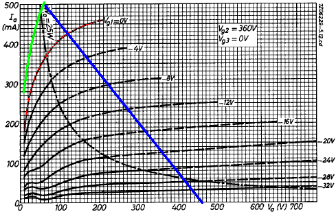
The red curve is the zero grid voltage curve for a 360V screen. The green curve is our estimate for a 450V screen.

|
Guitar Amplifier Electronics: Circuit Simulation - know your design works by measuring performance at every point in the amplifier. |
The output transformer impedance is 3.2kΩ plate-to-plate. For Class B, or Class AB that is close to Class B, the effective impedance is one fourth this value, or 800Ω. A plate voltage swing of 400V thus creates a plate current swing of 400V / 800Ω = 500mA. This is the blue load line in the graph.
We could use the green curve to estimate output power, but the result would be too high by a wide margin. First, it ignores output transformer and speaker losses. Moreover, it assumes no power supply sag, which lowers screen and plate supply voltages and reduces maximum output swing. For the Fender Bassman 5F6-A, for example, full power is about 56 watts without sag and 39 watts at full sag.2 Finally, it doesn't consider increased screen current, which creates a larger voltage drop across the screen resistors.
With a conservative estimate of 60V sag at full power, the screen voltage decreases to 390V minus some additional DC drop across the choke and an additional drop across the screen resistors, putting us close to the published curve for a 360V screen. Plate voltage swing is then 400V - 80V = 320V peak and 400mA peak, which creates 128W peak and 64W RMS for a sinewave. Output transformer loss is in the neighborhood of 10 percent, so we can estimate a maximum power output of 57W RMS. The JCM800 Model 2204 is generally classified as a 50-watt amp.
References
1Dave Hunter, The Guitar Amp Handbook, (Milwaukee: Backbeat Books, 2015), p. 49.
2Richard Kuehnel, Circuit Analysis of a Legendary Tube Amplifier: The Fender Bassman 5F6-A, 3rd ed., (Seattle: Pentode Press, 2009).
3Richard Kuehnel, Guitar Amplifier Electronics: Basic Theory, (Seattle: Amp Books, 2018), pp. 142-153.


