Circuit Analysis of the Gibson GA-5 Les Paul Junior
The Gibson GA-5 was created in 1954 as a low-power practice amp to accompany the Les Paul Junior guitar. Today it is a highly regarded studio amplifier. The circuit is almost identical to the Fender Champ 5C1 and uses the same tubes: a 5Y3 full-wave rectifier, a 6V6/6AQ5 beam power tetrode, and a 6SJ7 sharp-cutoff pentode.
6SJ7 Preamp
Here is the preamp circuit.
The inverted L network at the guitar input jack is identical to the Champ 5C1 but with different parts values: 47kΩ instead of 75kΩ, 10MΩ instead of 5MΩ. The resistors form a voltage divider, but the shunt resistance is so much larger than the series resistance that there is very little signal attenuation: 0.13dB for the Fender and 0.04dB for the Gibson.
Grid-Leak Bias
Modern amps do not have a coupling capacitor at the guitar input. It is needed here because of the unusual biasing method. The cathode is connected directly to ground without a cathode resistor. Normally this would bias the grid at 0V. The 10MΩ grid leak resistor, however, creates a substantial voltage drop for even a tiny amount of current. When the grid voltage swings positive, grid current flows from the grid to the cathode through the tube. This current must come from somewhere and there are only two possible sources: the 10MΩ grid leak or the 47kΩ resistor in series with the output impedance of the guitar circuit, which is relatively small. The latter path is the most lucrative - grid current flows from the driving circuit, through the capacitor, and to the grid.

|
Guitar Amplifier Electronics: Fender Deluxe - from TV front to narrow panel to brownface to blackface Reverb |
Unless there is a catastrophic breakdown, electrons do not jump the gap between the plates of a capacitor. The only way the capacitor can supply current is to release electrons from one plate and accumulate electrons on the other plate, causing it to charge. This is how grid bias is established. This technique, which is known as a shunt-type grid-leak bias, has three main ingredients: a coupling capacitor, a large grid-leak resistor, and a grounded cathode.
DC Operating Conditions and Input Headroom
There is a 128V drop across the 220kΩ plate load resistor. According to Ohm's Law, the plate current is
128V / 220kΩ = 0.6mA
Plate dissipation is
(162V)(0.6mA) = 97mW
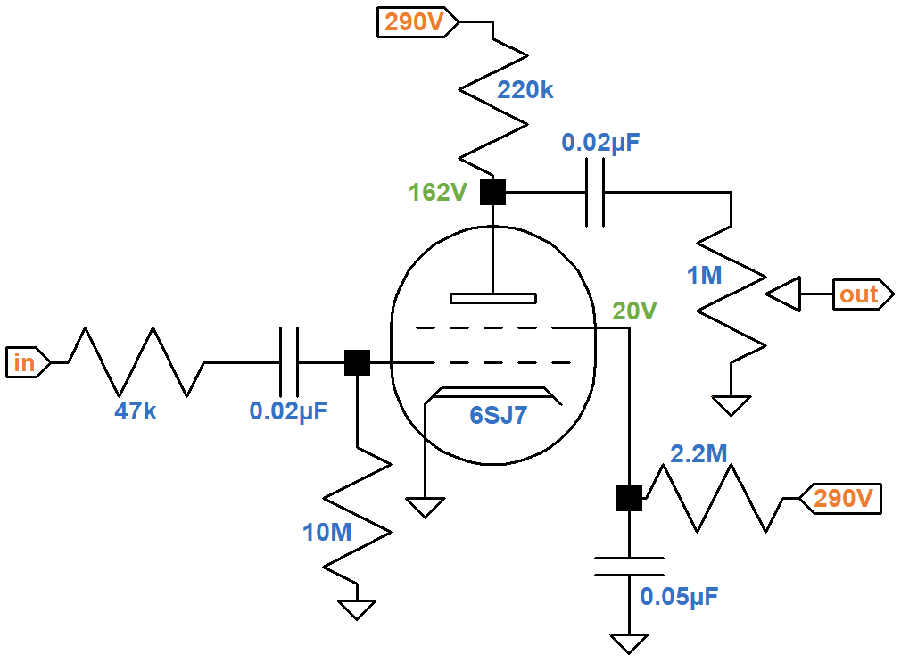
This is well within the 2.5W limit for a 6SJ7. The blue curve shown here on the 6SJ7 transfer characteristics represents an eyeball estimate for a 25V screen.
The intersection of the two red lines represents an imagined 20V curve and a plate current of 0.6mA. Reading from the horizontal axis, the DC grid bias looks to be about -0.4V. The imagined curve reaches cutoff at about -1.5V, so the grid controls plate current over a range of +0.4V to -1.1V relative to its DC operating point. If the guitar signal exceeds +0.4V, the stage reaches overdrive, which is not likely to happen with single-coil pickups. Input headroom for the preamp is therefore 400mV peak (-11dBV).

|
Guitar Amplifier Electronics: Basic Theory - master the basics of preamp, power amp, and power supply design. |
There is a 270V drop across the 2.2MΩ screen resistor, indicating that the DC screen current is
270V / 2.2MΩ = 0.12mA
Screen dissipation is
(20V)(0.12mA) = 2.4mW
This is well within the 700mW rating for a 6SJ7.
Voltage Gain for the Pentode Preamp
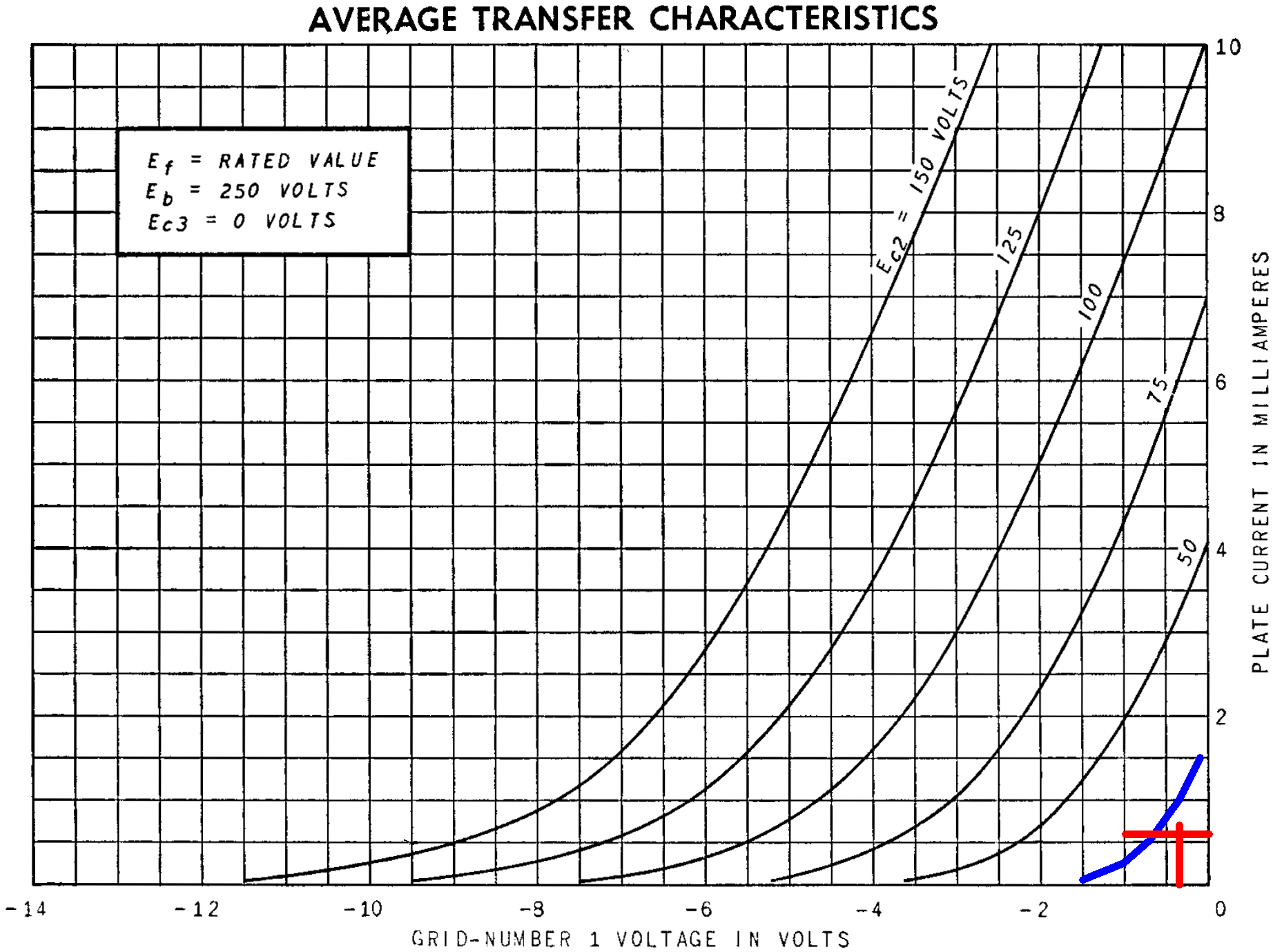
Another eyeball estimate for a 25V screen curve is shown here in blue.
For a 20V screen and a -0.4V grid, the transconductance is about 1100 micromhos, i.e. 1.1 milliamps per volt. Multiplying by the plate load resistor value, the unloaded voltage gain is
(1.1mA/V)(220kΩ) = 242 (48dB)
This applies when the tube operates on small signals that keep it operating within its linear range. For large signals, transconductance is not a constant, as shown by the graph.
The plate load resistance of a pentode is very high, so the output impedance is approximately equal to the plate resistor value: 220kΩ. The stage drives a 1MΩ volume control, which represents the AC load.
According to the Coupling Capacitor calculator, the 0.02μF value is large enough to provide a flat response. There is only a tiny fraction of a dB attenuation at 82Hz compared to midrange.
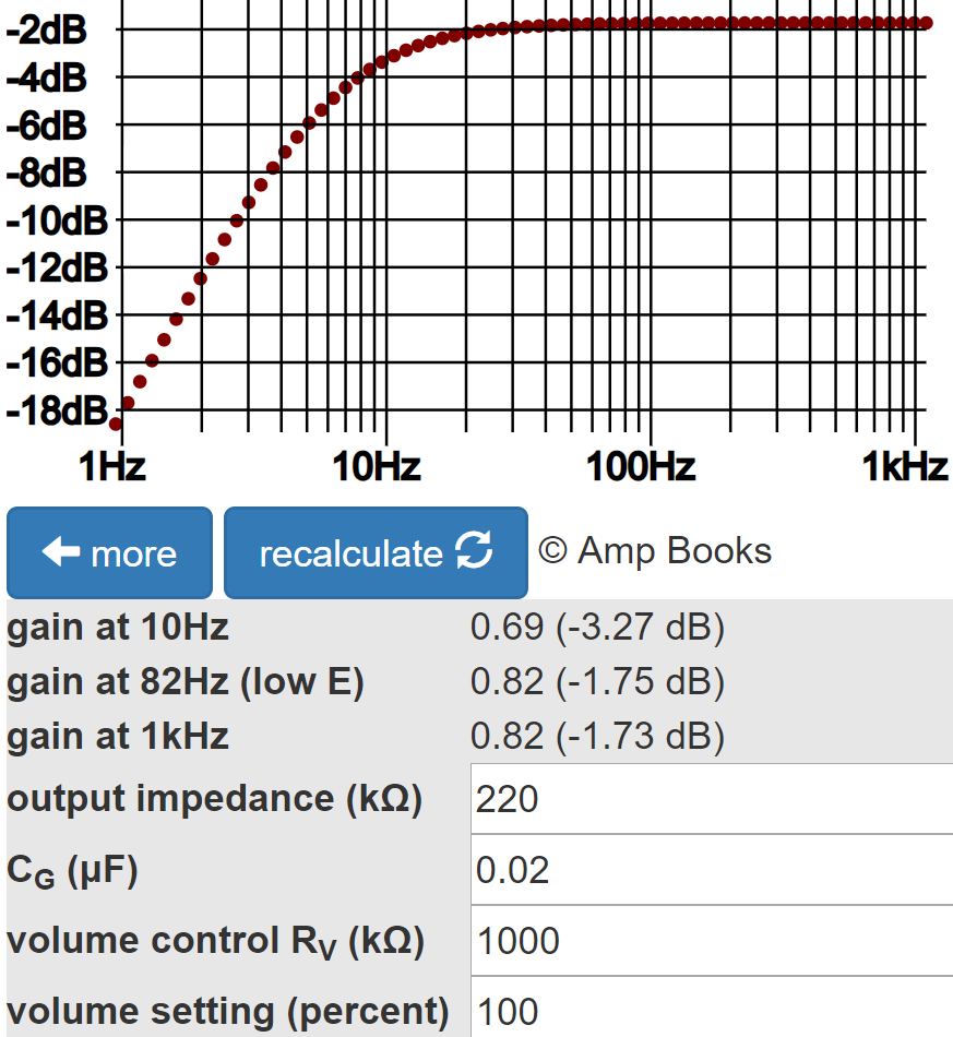
The calculator indicates that midrange loaded voltage gain for small signals is 1.7dB less than the unloaded gain, making the loaded gain 46.3dB.

|
Fundamentals of Guitar Amplifier System Design - design your amp using a structured, professional methodology. |
Power Amp DC Operating Conditions
Here is the 6V6 power amp.

The plate is at 345V relative to ground and the screen is at 290V. The cathode voltage is 17V relative to ground, so the plate-to-cathode and screen-to-cathode voltages are 328V and 273V, respectively. The blue curve shown here on the transfer characteristics is an eyeball estimate for a 273V screen.
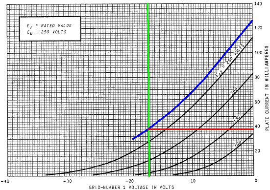
The green line represents a grid voltage of -17V. From where it intersects the curve we get an idle plate current estimate of 38mA. Plate dissipation at idle is
(328V)(38mA) = 12W
This is right at the limit of the 6V6. By examining the transfer characteristics for screen current at the same grid voltage, shown below, we observe that the idle screen current is approximately 3mA.
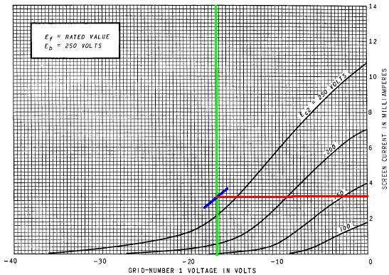
This makes the total current through the cathode at idle equal to 41mA, so by Ohm's Law the voltage drop across the cathode resistor is (41mA)(470Ω) = 19V, which is 12 percent higher than what the curves for an average 6V6 tell us. In the plus-or-minus 20 percent world of vacuum tube electronics, this is reasonable.

|
Guitar Amplifier Electronics: Circuit Simulation - know your design works by measuring performance at every point in the amplifier. |
Other Characteristics
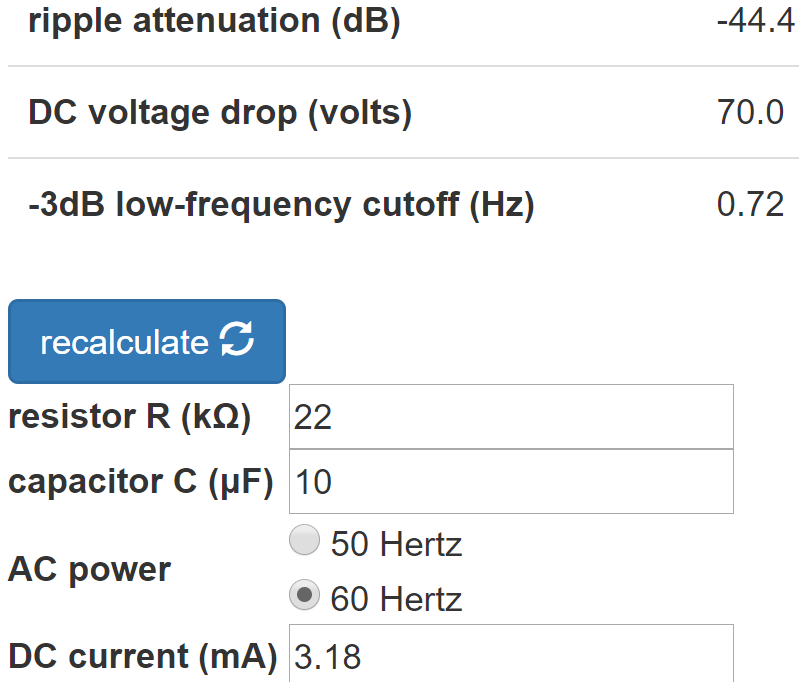
There are two RC ripple filters.
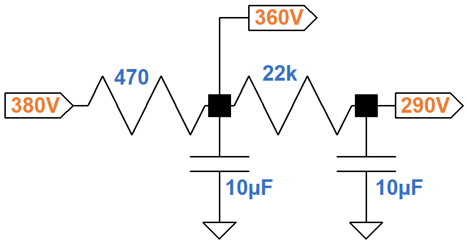
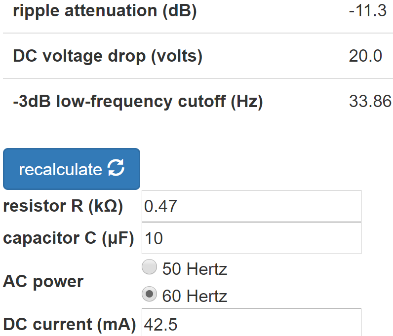
According to the RC Ripple Filter Calculator, there is 11dB of ripple attenuation (for 60Hz AC) across the 470Ω resistor and 44dB attenuation across the 22kΩ resistor.
At the cathode there is 470Ω in parallel with the reciprocal of 6V6 transconductance, which is about 4mA/V. The effective cathode impedance is therefore 163Ω. This makes the break frequency for the 20μF cathode bypass capacitor equal to
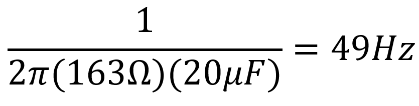
So the cathode is fully bypassed for guitar frequencies. This means that the input signal amplitude needed to drive the power amp to full power is equal to the DC grid bias. We can conclude that the GA-5 power amp has an input sensitivity1 of about 17V.
Output Power
Here are the 6V6 plate characteristic curves for a grid voltage of zero.
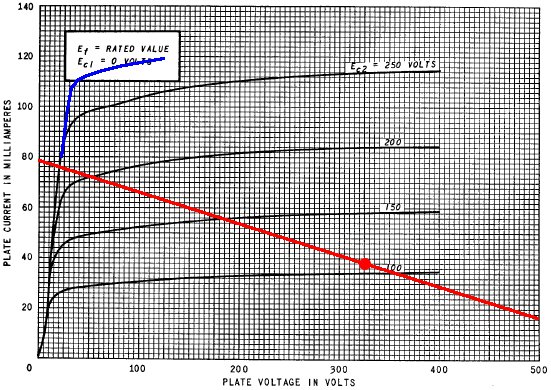
The blue curve depicts an estimate for a 273V screen. The DC operating point is represented by the red dot. The load line for an 8kΩ output transformer (the red line) intersects the diode line well below the knee of the curve, which is where the data sheet recommends. When the grid voltage increases from an idle value of -17V to a maximum of zero volts, the plate voltage drops by 305V and the plate current increases by 38mA, so the output power before transformer losses is approximately
(38mA)(305V) / 2 = 5.8W
Reference
1Richard Kuehnel, Guitar Amplifier Electronics: Circuit Simulation, (Seattle: Amp Books, 2019).
2Richard Kuehnel, Guitar Amplifier Electronics: Basic Theory, (Seattle: Amp Books, 2018).


