Circuit Analysis of the Fender Deluxe 5E3

In 1954 Elvis Presley recorded "That's alright, Mama" at Sam Phillips' studios in Memphis, Tennessee. More than two decades later, Shelter Records produced Tom Petty and the Heartbreakers' "Breakdown." Whether it's the mids-heavy fang of Scotty Moore's double stops or the focused magnetism of Mike Campbell's blues riffs, there is no mistaking the unmitigated glory of a well-tempered guitar plugged into a late 1950's tweed Deluxe. Guitar World calls it one of the most iconic guitar amps of all time.
"Introduced in 1948, the Fender Deluxe was praised for its dynamic, harmonically rich overdrive and compression. It was offered in numerous configurations and designs over the years, but the most desirable model is the 5E3 narrow-panel Deluxe, built from 1955 to 1960 and offered in a tweed-covered cabinet." 1
There is no bigger fan of the 5E3 than Neil Young.2
At the core of Young's amplifier setup is a piece of gear as essential to his sound as [his 1953 Gibson Les Paul goldtop] Old Black: the 1959 tweed Fender Deluxe he's used since the late Sixties. A small, 15-watt unit, with just two volume knobs and a shared tone control, this amp, says [Young's guitar tech Larry] Cragg, "makes all the sound. Onstage, as loud as everything gets, that's what you hear."

The 5E3 is the most cloned amp of all time. Its elegantly straightforward signal chain maximizes tone and minimizes parts count, making it a favorite for kit makers and kit builders alike.
"The Tweed Deluxe is such a seminal amplifier, is so desirable and (in its original form) so expensive, that there are at least 30 or 40 companies out there making clones or variants of it, either as kits or as completed amplifiers. ... Part of the reason for this plethora of plagiarism is that the 5E3 circuit is extremely simple, and so anyone who can hold a soldering iron can probably build one fairly easily." -Bob Thomas3
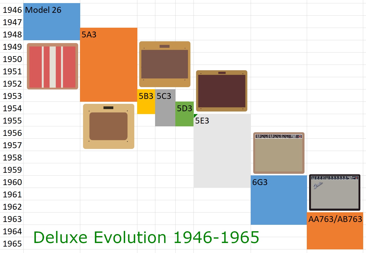
The Deluxe 5E3 represents evolutionary development based on a history of modifications to a basic architecture. The 5A3/5B3 takes the Deluxe Model 26 and gives it grid-leak bias, a new phase inverter tube, and higher DC supply voltages. The 5C3 applies a smidgeon of negative feedback. The 5D3 reverts back to cathode bias, eliminates the feedback, and transitions to 9-pin triodes. The 5E3 tweaks the design further.
Many would say the Deluxe reaches a pinnacle of design with the 5E3, becoming the ultimate tone machine for public performance and recording.
"Ah, the glorious narrow-panel 5E3 tweed Fender Deluxe. This is such a ubiquitous design that there's no point detailing it. Hell, it's in our blood, part of our shared consciousness, hardwired into every guitarist's genetic memory." -Dave Hunter4
First Stage 12AY7 Preamp
The first stage has two channels that share a fully-bypassed 820Ω cathode resistor and 25μF cathode bypass capacitor. The equivalent values for one triode are 1.64kΩ and 12.5μF, respectively.
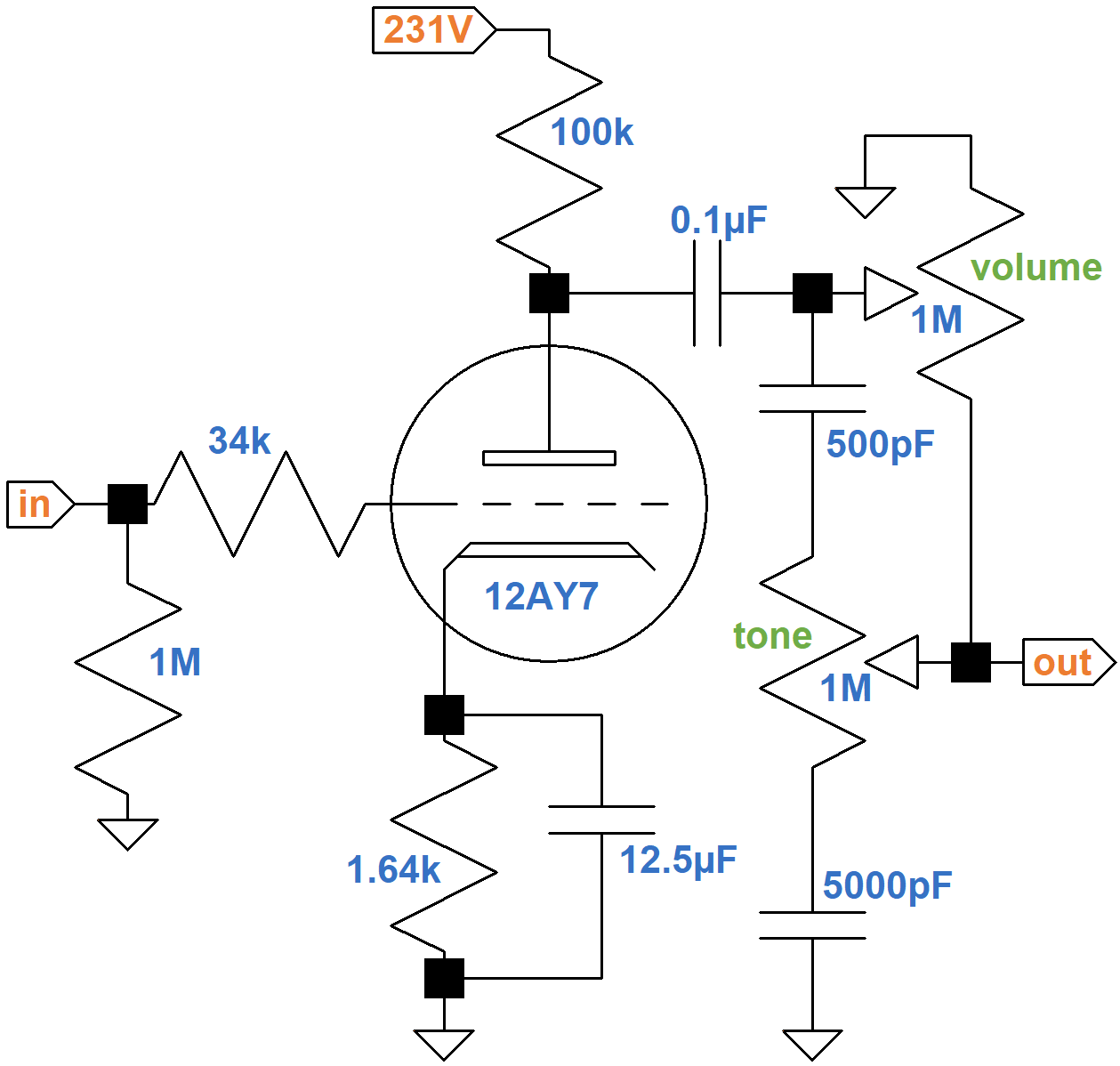
The #1 input jack connects to a classic gamma network comprised of a 1MΩ grid leak resistor and a 34kΩ effective grid-stopper resistance comprised of two 68kΩ resistors in parallel. Across the network there is unity (0dB) midrange gain and very little treble attenuation due to Miller capacitance.5 The purpose of the 34kΩ grid-stopper resistance is to attenuate only radio frequencies.
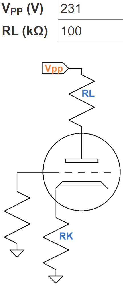
The 231V plate supply voltage is an estimate. According to the 12AY7 calculator, the DC grid bias is about -1.9V.
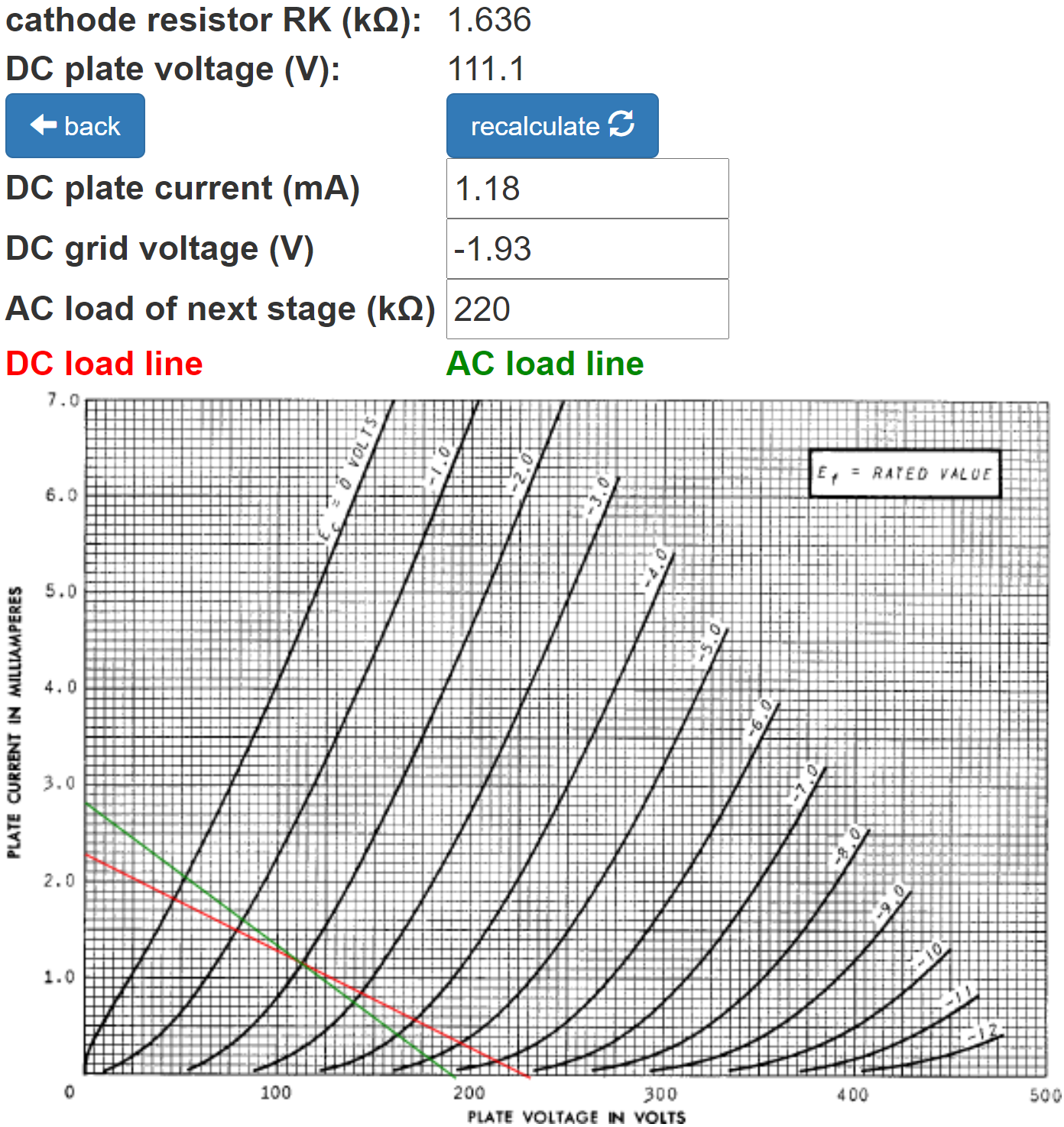
An arbitrarily small AC load of 123kΩ is used in the calculator to rotate the AC load line clockwise to provide a better marker for the DC operating point. The actual AC load varies substantially with the settings of the volume and tone controls. Moreover, frequency has a big impact. At 82 Hz, the 0.005μF tone control capacitor has a relatively large reactance of 379kΩ. For the 500pF capacitor it is even greater: 3.79MΩ. At 10kHz, the reactances decrease to only 318Ω and 3.18kΩ, respectively, which are quite low compared to the resistances of the potentiometers. The AC load therefore varies greatly with knob position and frequency. Based on SPICE simulation,6 here is the frequency response in dB versus frequency in hertz with the volume control set to 10-percent resistance.
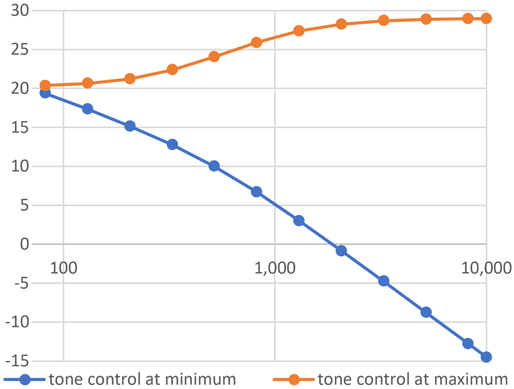
The tone control is at minimum (blue) and maximum (orange). The volume control for the other channel is set to minimum.
Second Stage 12AX7 Voltage Amplifier
The second stage is a classic voltage amplifier with a fully bypassed cathode resistor.
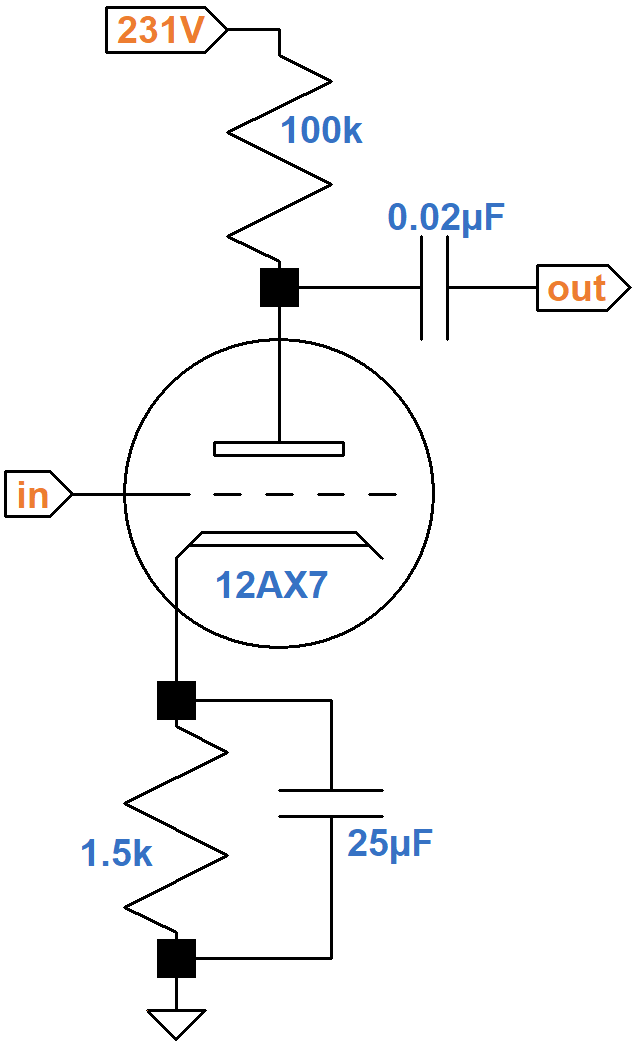
According to the 12AX7 calculator, the DC grid bias is about -1.2V.
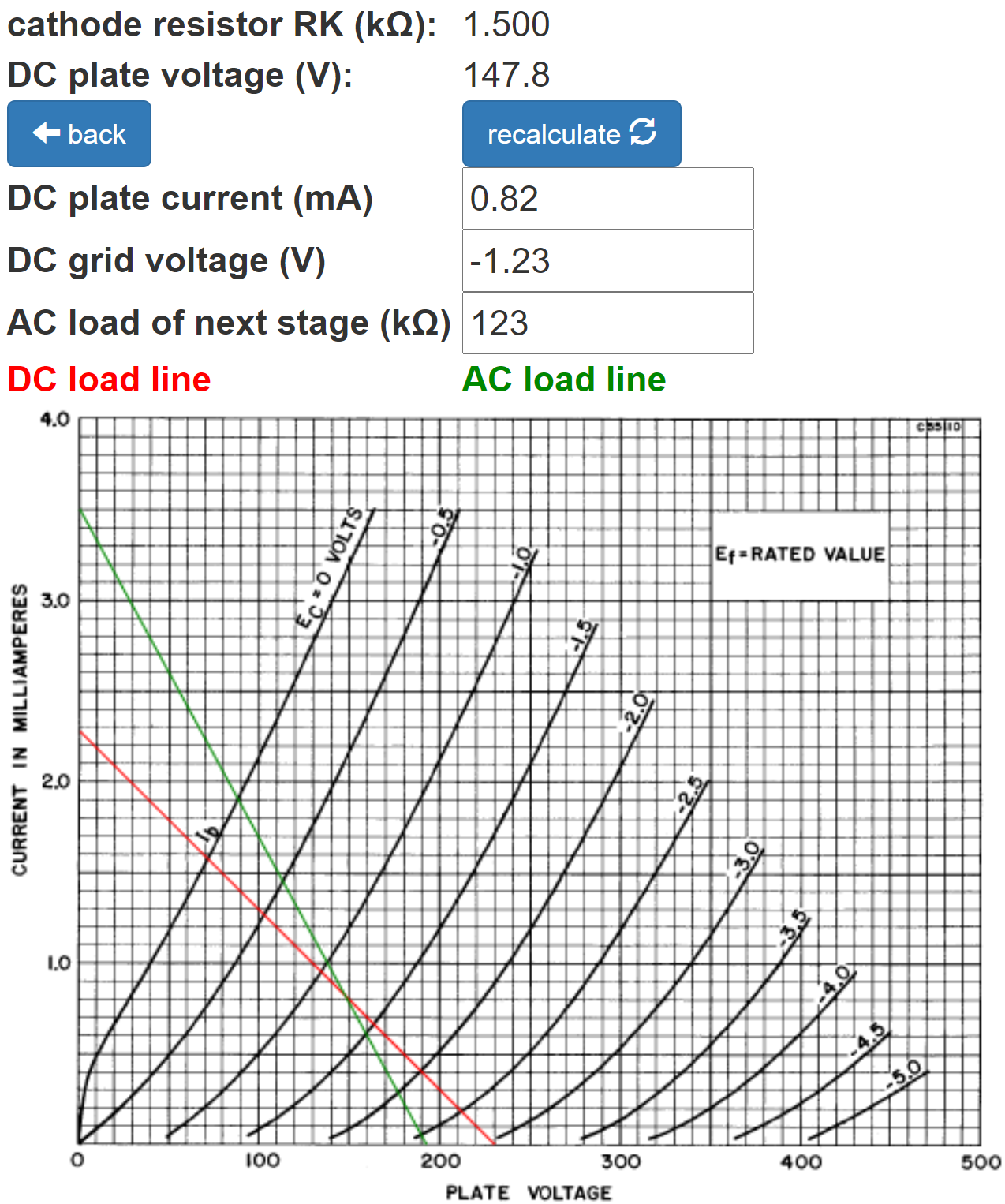
The AC load is again set to an arbitrarily low value of 123kΩ to better mark the DC operating point. The input impedance of the next stage is greater than 1MΩ, representing a very light load, so the actual AC load line is rotated only slightly clockwise from the DC load line.
According to the red DC load line, which approximates the actual AC load line, the grid voltage can swing positive by 1.2V from the DC operating point, making input headroom equal to 1.2V peak (-1.4dBV). If we assume a first stage gain of 20dB, the guitar signal at the input jack needed to overdrive the second stage is is -21.4dBV (120mV peak), which can be achieved by hot pickups.
According to the Preamp Gain and Output Impedance calculator, the unloaded gain and output impedance are 36dB and 38kΩ, respectively.
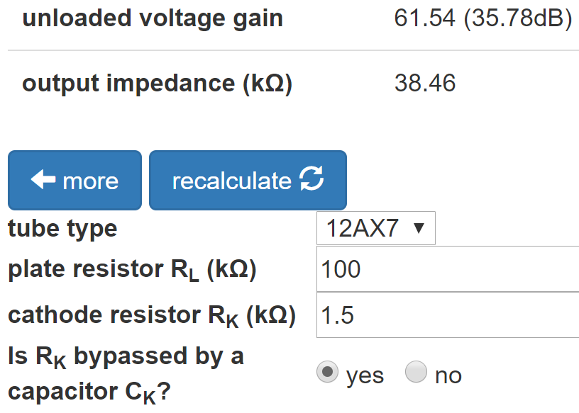
Because of the light AC load of the next stage, the loaded gain is approximately the same as the unloaded gain.
Phase Inverter
The 5E3 uses a concertina phase splitter (also called a cathodyne or split-load inverter).7
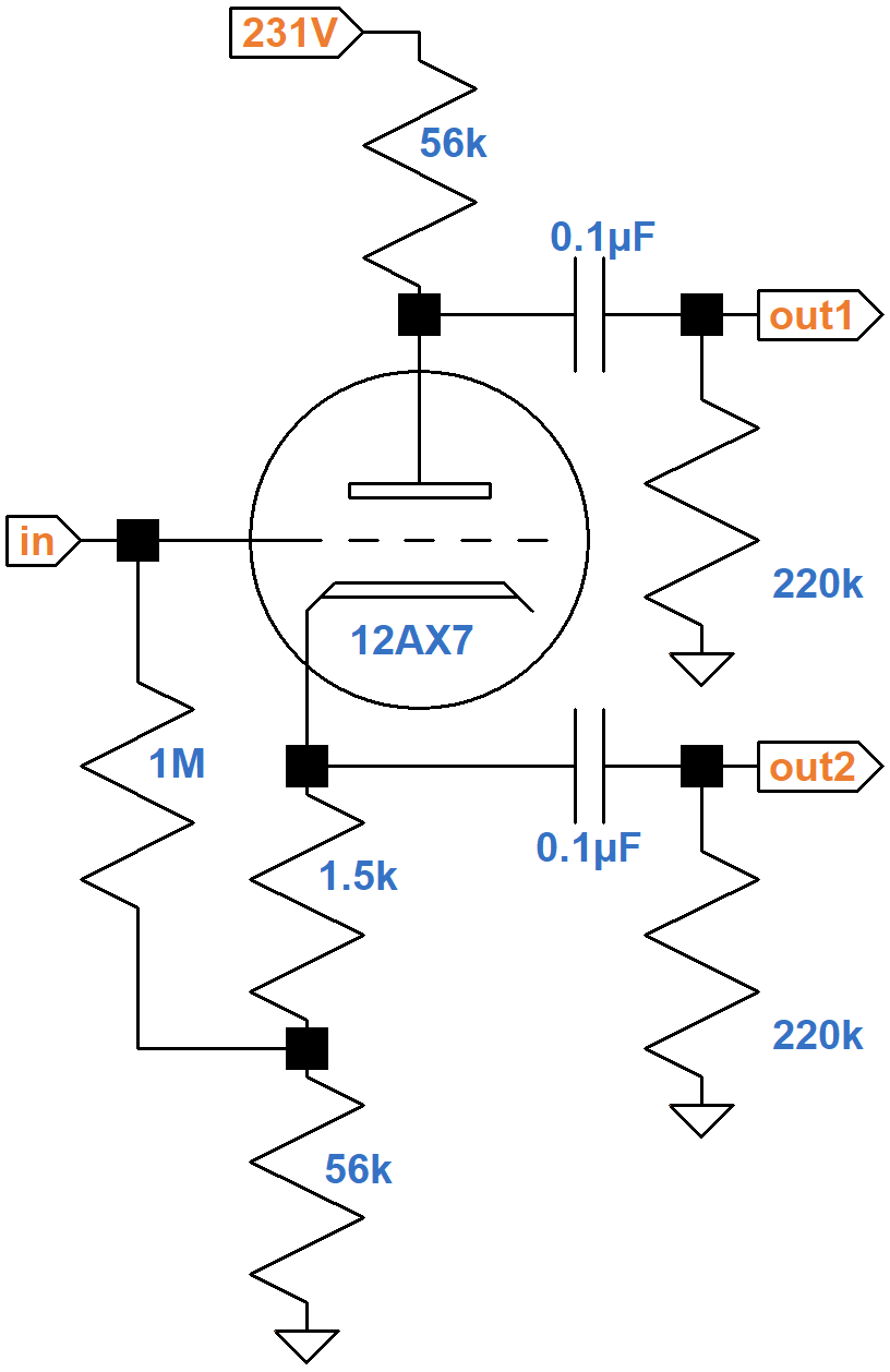
The DC load line, shown here in red, joins the DC plate-to-cathode voltage of 231V on the X axis to a Y-axis plate current of
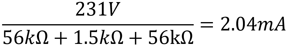
If the grid voltage is -1V or -1.5V, then the plate current is
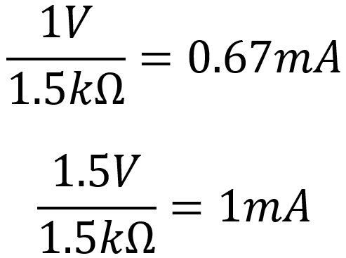
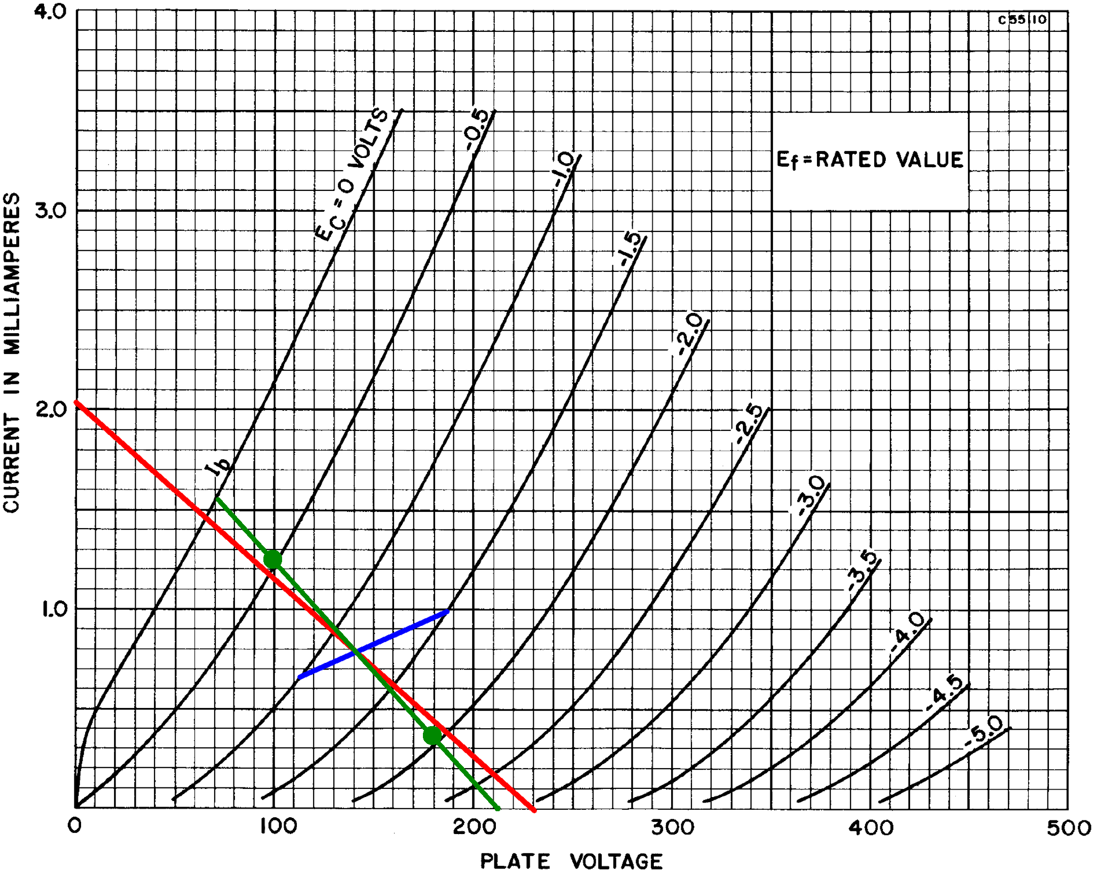
These values define the blue line segment. The DC operating point is defined by their intersection: a grid-to-cathode voltage of -1.2V, a plate-to-cathode voltage of 140V, and a plate current of 0.8mA.
For an AC signal, each 56kΩ resistor is in parallel with a 220kΩ grid-leak resistor for an AC load of 45kΩ. (The extra 1.5kΩ from the cathode to ground, which introduces a slight amount of imbalance, can be ignored.)
If the plate current swings from the DC operating point value of 0.8mA to 0mA, then the plate-to-ground voltage swings positive by (0.8mA)(45kΩ) = 36V. The cathode-to-ground voltage swings negative by the same amount, so the plate-to-cathode voltage swings positive by 2(36V) = 72V. The green AC load line therefore contains the endpoint defined by 0mA and 140V + 72V = 212V. The slope of the load line is
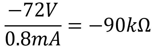
This makes sense, because for audio signals the plate and cathode loads are each 45kΩ. The triode is therefore in series with 45kΩ + 45kΩ = 90kΩ.
At full power, the plate-to-ground voltage swings by 20.5V peak, matching an estimated 6V6 DC grid bias of -20.5V. The cathode-to-ground voltage swings by 20.5V with opposite phase, so the plate-to-cathode voltage swings by 41V peak. This extent of swing is marked by the green dots on the AC load line. According to the AC load line, the grid-to-cathode voltage swings by about 0.7V peak.
Maximum plate-to-cathode voltage swing is about 72V peak, representing 36V peak at the plate output and the cathode output, so at full power the phase inverter operates slightly more than halfway to overdrive.
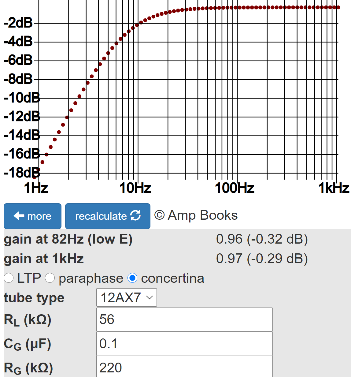
The phase inverter has approximately unity voltage gain. According to the Phase Inverter Bass Response calculator, the 0.1μF coupling capacitors provide a very flat response.
Power Amp
Here is the power amp.
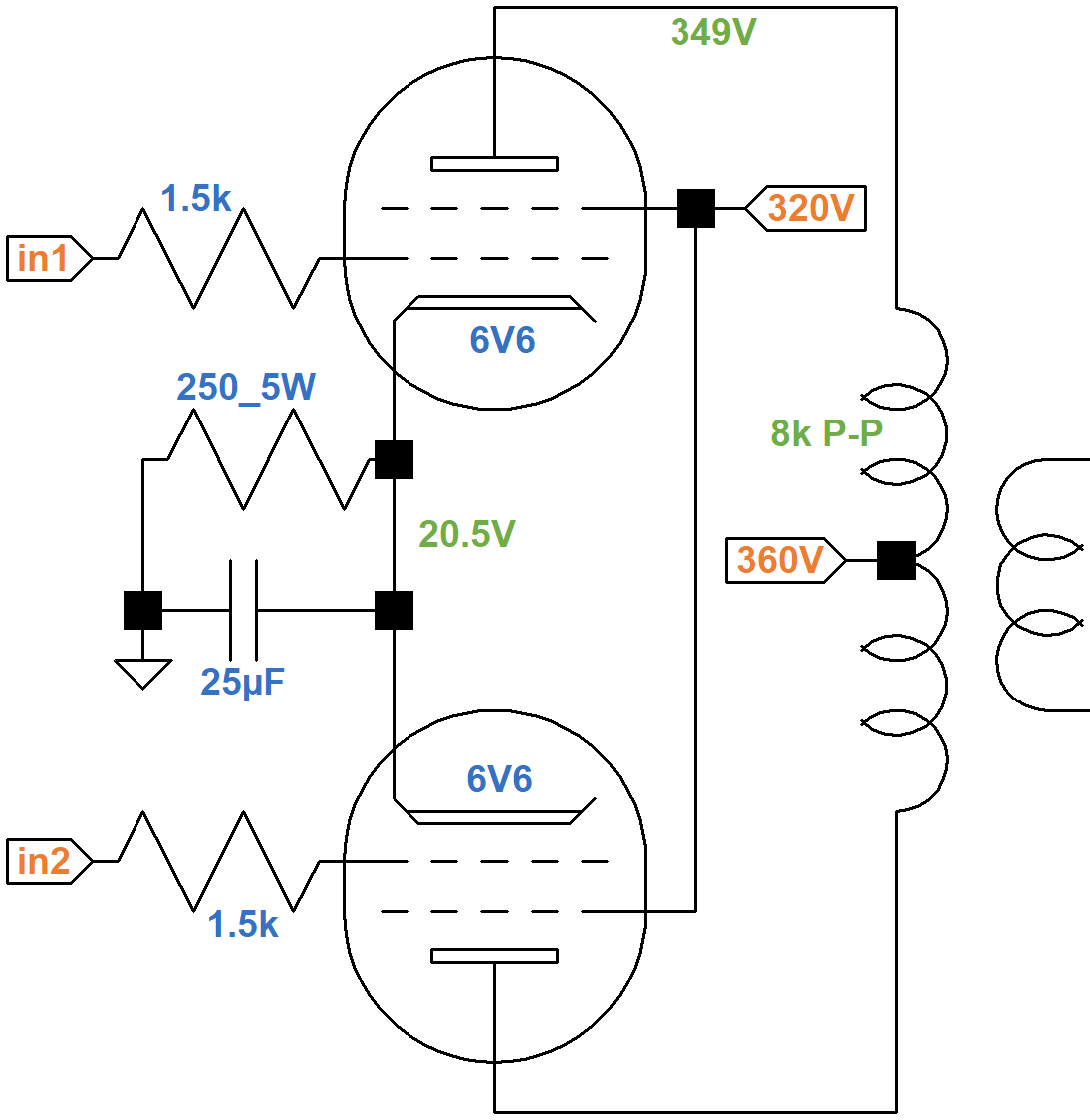
The plate-to-cathode voltage is 328V and the screen-to-cathode voltage is 299V. The current through the 250Ω cathode resistor is
20.5V / 250Ω = 82mA
This translates to 41mA per tube. Estmated screen transfer characteristics show about 2mA for an imagined 299V screen curve and a -20.5V grid, as indicated by the red dot.
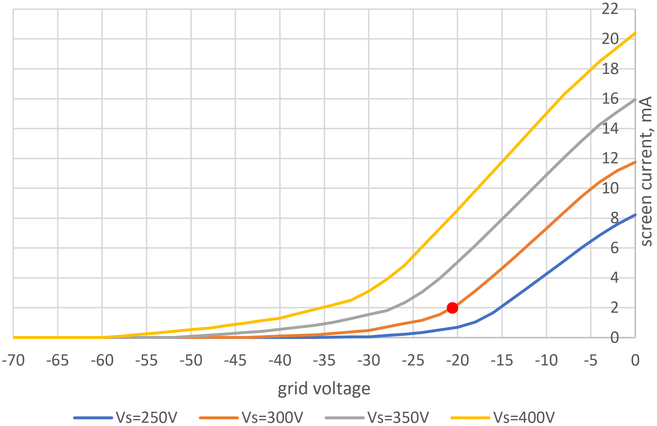
The plate current is 41mA - 2mA = 39mA per tube.
If the plate-to-cathode voltage swings from 328V to 0V across an effective 2kΩ transformer primary impedance (8kΩ plate-to-plate), net plate current swings to
The endpoints for the AC load line are therefore 0V, 164mA and 328V, 0mA, as shown by the red line on estimated 6V6 plate characteristics for a 0V grid.
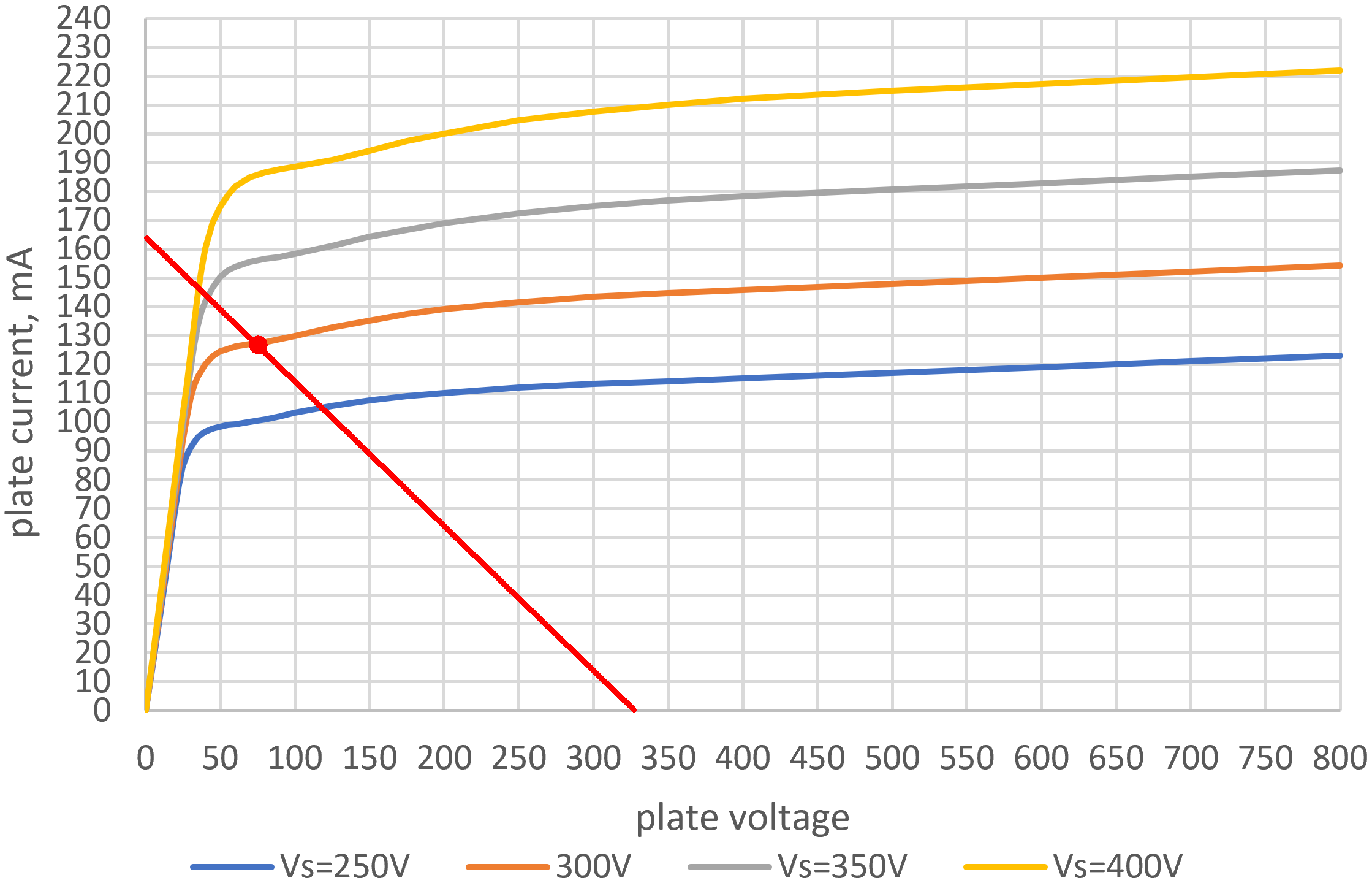
The load line intersects an imagined curve for a 299V screen at 75V, 128mA (depicted by the red dot) for an output power of approximately
This assumes the power supply voltages do not sag at full power.
In Summary
The 5E3 Deluxe has just three knobs and no superfluous features to clutter the signal path. It rejects out of hand the benefits of a feedback circuit or a fixed bias supply. It eschews the complexity of added features and creates a guitar amp in its purest form. Mike Campbell is a big fan.
"I like little amps, so I use a Fender Princeton and a tweed Deluxe." -Mike Campbell8
References
1Damian Fanelli, Christopher Scapelliti and Tom Gilbert, "The 10 Most Iconic Guitar Amps of All Time," Guitar World, April 24, 2020.
2Richard Bienstock, "Neil Young: Ragged Glory," Guitar World, October 15, 2009.
3Bob Thomas, "Torres Engineering", Sound on Sound, February 1, 2014.
4Dave Hunter, Amped, (Minneapolis: Voyageur Press, 2012), p. 64.
5Richard Kuehnel, Guitar Amplifier Electronics: Basic Theory, (Seattle: Amp Books, 2018), pp. 71-72.
6Richard Kuehnel, Guitar Amplifier Electronics: Circuit Simulation, (Seattle: Amp Books, 2019).
7Richard Kuehnel, Guitar Amplifier Electronics: Basic Theory, (Seattle: Amp Books, 2018), pp. 130-134.
8Joe Bosso, "The Waiting", Guitar Player, May 2020, p. 54.


