Circuit Analysis of the Fender Champ 5E1
"For many players and amp-o-philes alike, the tweed Fender Champ is ground zero for vintage tube amps. The simplicity of this design and part and parcel to that, the purity of its tone make it a universal starting point for the virtues of tube amps et al for many players. As such it's a vintage amp that every guitarist should experience at least once." -Dave Hunter1
The First Stage Preamp
From a technical perspective, the tweed Champ is an elegantly simple design. Here is the front end.

The #1 input jack connects to a classic gamma network comprised of a 1MΩ grid-leak resistor and an effective 34kΩ grid-stopper resistance comprised of two 68kΩ resistors in parallel. Across the network there is very little treble attenuation due to Miller capacitance.2 The purpose of the grid stopper is to attenuate only radio frequencies.
According to the 12AX7 calculator, for a plate supply voltage of 260V, a 100kΩ plate load resistor, and a 1.5kΩ cathode resistor, the DC grid bias is -1.4V. Fender's measured value is -1.5V.


The green AC load line is based on the 1MΩ AC load established by the volume control. It indicates that the grid voltage can swing from 0V to -3V, so the bias is relatively neutral and input headroom is 1.4V peak (-0.1dBV), well beyond the output of a typical pickup.
The Cathode Bypass Capacitor calculator shows that the 25μF capacitor fully bypasses the cathode resistor.

Gain at 82Hz, low E on a guitar with standard tuning, is attenuated by less than a tenth of a dB compared to midrange.
The Preamp Gain and Output Impedance calculator shows that the unloaded gain and output impedance are 35.8dB and 38kΩ, respectively.

The output impedance and 1MΩ volume control form a voltage divider with a voltage "gain" of
1MΩ / (1MΩ + 38kΩ) = 0.96 (-0.3dB)
The loaded gain, measured from the grid of the first triode to the top of the volume control, is therefore 35.5dB.
The Coupling Capacitor calculator shows that 0.02μF provides an adequate bass response.

Gain at 82Hz is down by less than a tenth of a dB. Gain at 10Hz, well below audio, is down by 2dB, which contributes to inter-stage plate supply decoupling.3
The Second Stage Power Amp Driver
The 1.5kΩ cathode resistor for the second stage is not bypassed by a capacitor, creating negative feedback from cathode degeneration.4
This reduces gain and increases input headroom. The top of the unbypassed cathode resistor also offers a convenient insertion point for negative feedback from the output transformer secondary.
The calculated DC grid bias for an average 12AX7 is -1.4V, just like first stage. Fender measures -1.5V. The second stage drives a 220kΩ load, which is lower than for the first stage, increasing the clockwise rotation of the AC load line around the DC operating point.

Idle plate current is 0.92mA. For the grid-to-cathode voltage to swing to 0V, the grid-to-ground voltage needs to swing positive by 1.4V plus an additional
(2mA - 0.92mA)(1.5kΩ) = 1.6V
i.e. 3V peak (+6.5dBV), representing input headroom.
According to the Preamp Gain and Output Impedance calculator, the unloaded gain and output impedance for the second stage are 30dB and 68kΩ, respectively.

Negative feedback from the output transformer secondary reduces gain by a modest 3.4dB.5
The Coupling Capacitor calculator verifies that 0.02μF provides an adequate bass response.

There is increased attenuation because of the increased AC load: 220kΩ compared to 1MΩ for the first stage.
The second stage does not have a grid-stopper resistor per se, but the volume control and output impedance of the first stage act as a series resistance for the Miller capacitance between the second triode's grid and cathode, forming a low-pass filter. Treble attenuation is greatest when the volume is set to about 50-percent resistance. If we assume about 250kΩ grid-stopper resistance in the coupling between the first and second stages, the Grid Stopper Resistor calculator shows about 3dB attenuation at the upper extreme of treble, which is inconsequential.

At other volume settings, treble attenuation is even less.
Treble attenuation in the coupling between the second stage and the power amp is extremely small for two reasons:
- a multi-grid power tube, which has much less Miller capacitance, and
- only about 68kΩ series resistance, which comes from the output impedance of the second stage.
Subtracting the loaded gain of the first stage, the input signal level needed to overdrive the second stage with the volume control set to maximum is +6.5dBV - 35.5dB = -29dBV (50mV peak). This level is within the capabilities of a single-coil pickup, so if the guitar controls and the Champ's volume control are set to maximum, expect second-stage overdrive. Long before then, however, the power amp exceeds its limits of headroom, which is 19V peak, as will be seen. Maximum second-stage plate voltage swing is about 3 times greater, so the power amp is the first stage to reach overdrive.
The Power Amp
The Champ has a single-ended,6 cathode biased power amp.

Fender's measured voltage across the 470Ω cathode resistor is 19 volts, so by Ohm's Law the current through it is 40mA. This is the current through the cathode, which is the sum of the plate and screen currents. Here are the screen transfer characteristics from a 6V6 data sheet.

The screen current is approximately 3mA. Subtracting 3mA from the cathode current, the plate current is 37mA. This is very close to the 36mA that can be estimated from the plate transfer characteristics shown here:

If we imagine a curve on the plate transfer characteristics corresponding to a screen voltage of 305V - 19V = 286V, we can envision the lower left end crossing into cutoff somewhere in the vicinity of -38 grid volts, so the grid swings from -38V to 0V, centered on the DC grid bias of -19V. The DC operating point is defined by a grid-to-cathode voltage of -19V, a plate current of 37mA, and a plate-to-cathode voltage of 286V.
The blue line shown here on the plate characteristics for a 0V grid represents a load line through the DC operating point for an output transformer with an 8kΩ primary impedance.

The load line intercepts an imagined curve for a 286V screen at a plate voltage of 15V and a plate current of 71mA. Power output is approximately half the product of peak voltage swing and peak current swing:
(286V - 15V)(71mA - 37mA) / 2 = 4.6W
The 5E1 Power Supply
The Champ 5E1 power supply uses a 250V-0V-250V RMS power transformer and a 5Y3GT vacuum tube rectifier.
They drive a capacitor input filter, an LC filter, and an RC filter.

The power supply needs to provide the plate and screen currents for two triodes and one power tube. At idle, the 12AX7 triodes each draw 0.9mA. The 6V6 screen draws 3mA and the plate draws 37mA, so the total load current is 42mA.
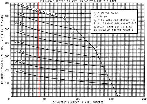
Without a load, the DC output of the power supply would be 354V, the peak output voltage for a 250V RMS power transformer secondary. According to the 5Y3GT data sheet, a 42mA load causes the voltage to sag to 290V, as shown here where the red line crosses the 250V RMS curve.
According to the LC Ripple Filter Calculator (assuming the choke has a DC resistance of 37.5Ω per henry, which is typical for a Champ replacement choke), the filter provides 24.7dB ripple attenuation.

The DC voltage drop is 6V, so the voltage for the plate and screen supply is 290V - 6V = 284V. This is within 7-percent of Fender's published value of 305V.
According to the RC Ripple Filter Calculator, the RC filter provides 42.5dB ripple attenuation.

Acknowledgment
Our thanks to Richard Grisel of Institut National des Sciences Appliquées de Rouen for his technical assistance with this page.
References
1Dave Hunter, Amped, (Minneapolis: Voyageur Press, 2012), p. 40.
2Richard Kuehnel, Guitar Amplifier Electronics: Basic Theory, (Seattle: Amp Books, 2018), pp. 71-72.
3Richard Kuehnel, Fundamentals of Guitar Amplifier System Design, (Seattle: Amp Books, 2019), pp. 100-113.
4Richard Kuehnel, Guitar Amplifier Electronics: Basic Theory, (Seattle: Amp Books, 2018), pp. 61-65.
5Richard Kuehnel, Guitar Amplifier Electronics: Basic Theory, (Seattle: Amp Books, 2018), pp. 145-150.
6Richard Kuehnel, Guitar Amplifier Electronics: Basic Theory, (Seattle: Amp Books, 2018), pp. 102-113.


