Ampeg Push-Pull 7591 Power Amp
There are shred-friendly Fenders and Marshalls, the classic tools of rock and blues, and then there are Ampegs, which appeal to an entirely different player.
"If you want a guitar amp with loads of headroom for country, jazz, or any medium-volume playing where you get all your overdrive from pedals, by all means seek out one of the superefficient Jet, Reverborocket, or Mercury models with firm 7591 output tubes." 1 - Dave Hunter
Let's examine the Ampeg Jet 12 push-pull power amp and the interesting pair of triode circuits that drive them.
The Power Amp
The Jet 12 does not include screen resistors.
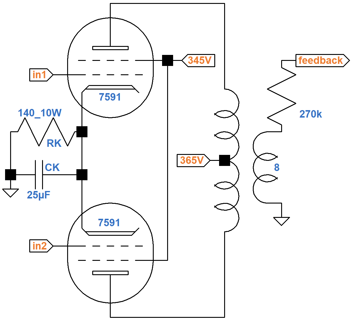
To prevent damage during overdrive, modern designs usually add at least a couple hundred ohms in series with the screens.
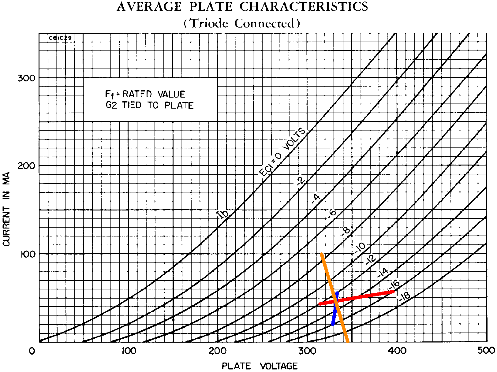
The screen and plate voltages are nearly the same, so we can use 7591 triode-connected curves to determine the DC operating point. The screen has a far greater influence on electron flow,2 so we will use 345V as the "plate" supply voltage for our triode. The triode's "plate current" represents the sum of the plate current and screen current, i.e. the total current that passes through the 140Ω cathode resistor. The current through the resistor is from two tubes, so the equivalent resistance for one tube is 280Ω. If the cathode voltage is 12V, 14V, or 16V, then according to Ohm's Law the plate current is
12V / 280Ω = 43mA
14V / 280Ω = 50mA
16V / 280Ω = 57mA
These three points create the two red line segments shown here.

|
Guitar Amplifier Electronics: Fender Deluxe - from TV front to narrow panel to brownface to blackface Reverb |
From another perspective, if the cathode voltage is 12V, 14V, or 16V, then the plate-to-cathode voltage is
345V - 12V = 333V
345V - 14V = 331V
345V - 16V = 339V
These points create the two blue line segments.
From a third perspective, if no current flows through the cathode resistor, there is no voltage across it and the plate-to-cathode voltage is 345V. If the plate current is 100mA, on the other hand, then the cathode voltage is
(100mA)(280Ω) = 28V
The DC plate voltage is therefore 317V. These two endpoints create the orange line. The intersection of these perspectives points to a DC grid bias of -13V for an average set of tubes.
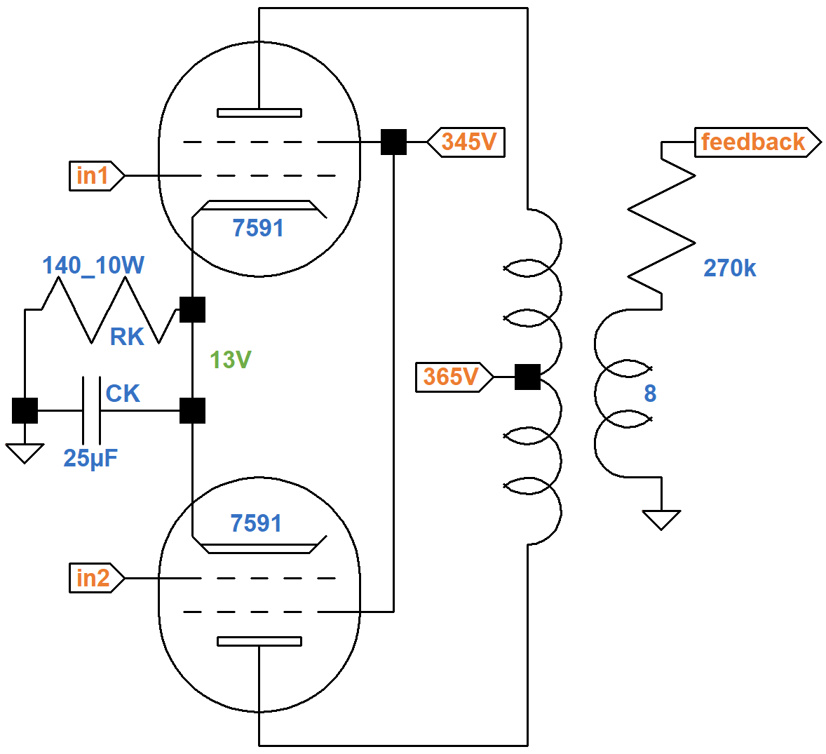
(Ampeg measures -15V.) The DC screen-to-cathode and plate-to-cathode voltages are
345V - 13V = 332V
365V - 13V = 352V

|
Guitar Amplifier Electronics: Basic Theory - master the basics of preamp, power amp, and power supply design. |
Assuming the tubes operate close to Class B, a 6.6kΩ plate-to-plate primary can be represented by the red 1.65kΩ load line shown here on the 7591 plate characteristics.
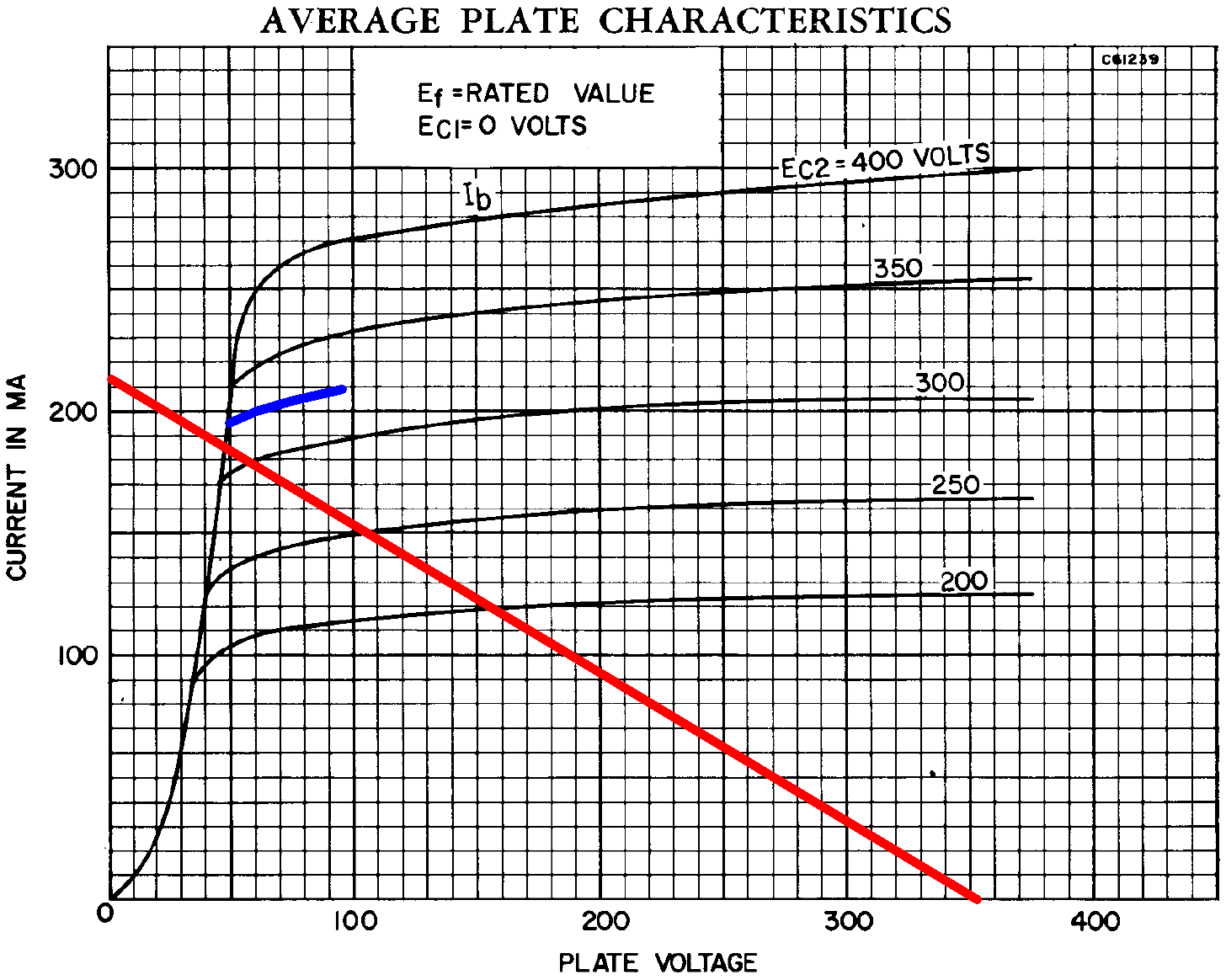
At the lower right is 352V. At the upper left is
352V / 1.65kΩ = 213mA
The load line intercepts a blue estimated curve for a 332V screen just below the knee.
At full power the plate voltage swings down to 48V and the plate current swings to 185mA, so output power is approximately
(352V - 48V)(185mA) / 2 = 28W

|
Fundamentals of Guitar Amplifier System Design - design your amp using a structured, professional methodology. |
Driver and Phase Inverter
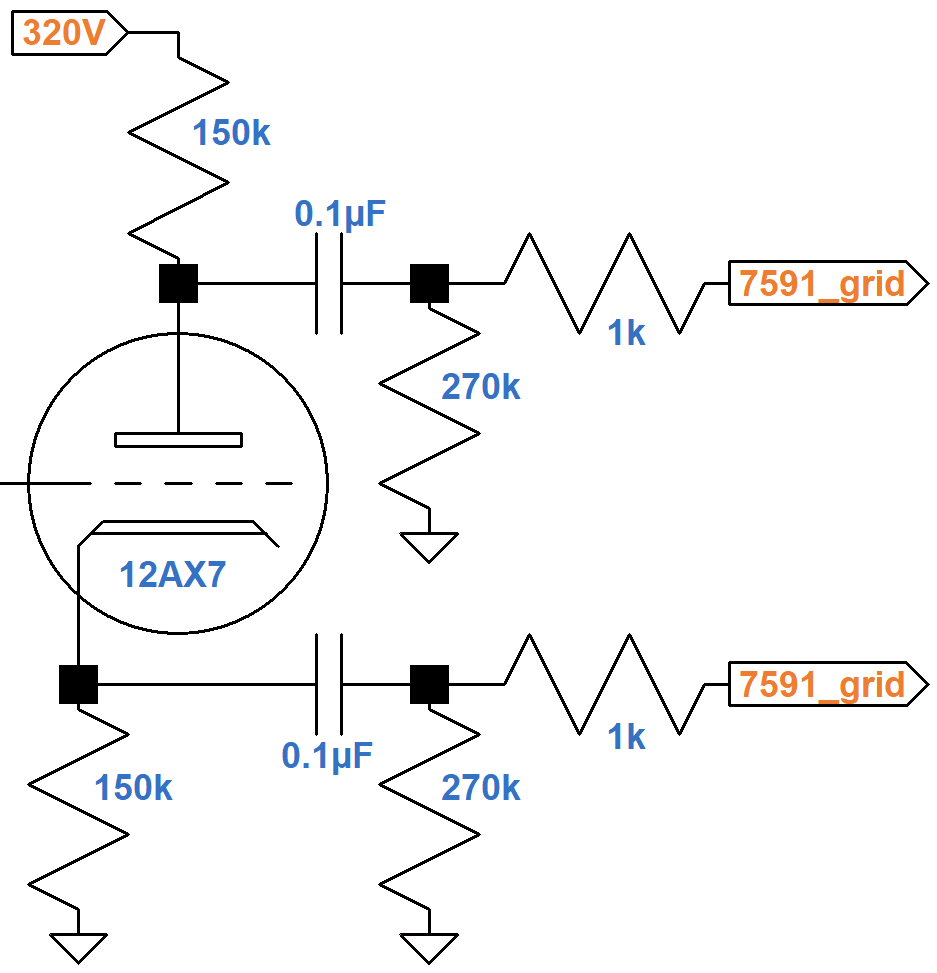
Upstream of the power amp is a voltage amplifier and a concertina (also called a split-load or cathodyne)3 phase inverter.
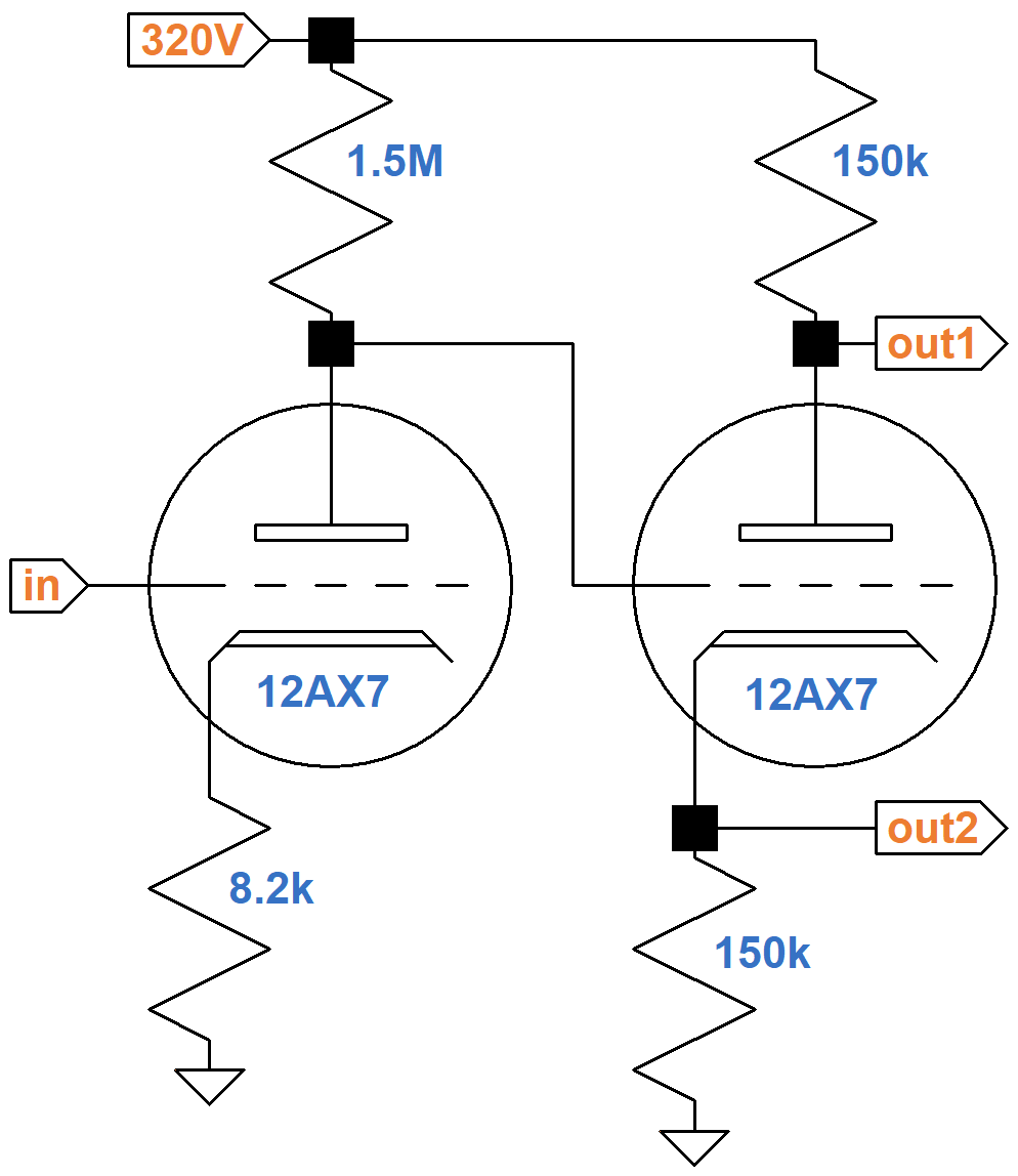
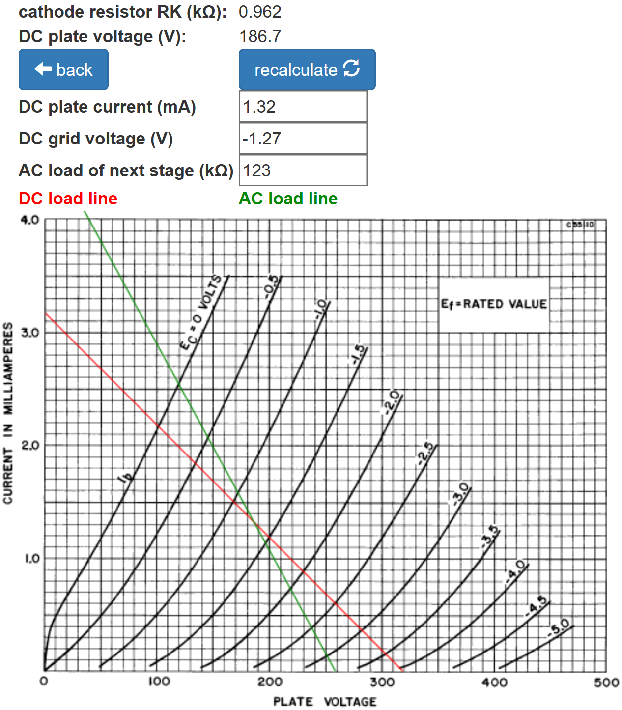
The input is at DC ground potential. According to the 12AX7 calculator, the DC plate-to-cathode voltage is 86V.

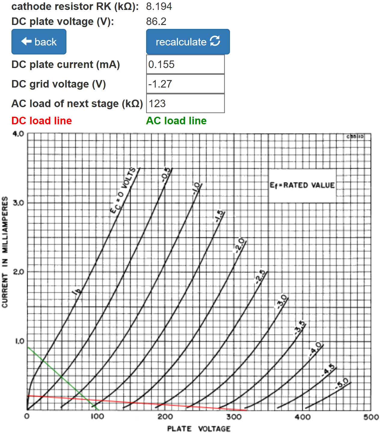
(The AC load is very light, so an arbitrary 123kΩ AC load has been entered so that the green AC load line can mark the DC operating point.) The DC grid bias is about -1V, so there is 87V between the plate and ground for an average tube. (Ampeg measures 80V.)

|
Guitar Amplifier Electronics: Circuit Simulation - know your design works by measuring performance at every point in the amplifier. |
According to the Preamp Gain and Output Impedance calculator, the gain is about the same as for a traditional 12AX7 preamp stage: 36dB.
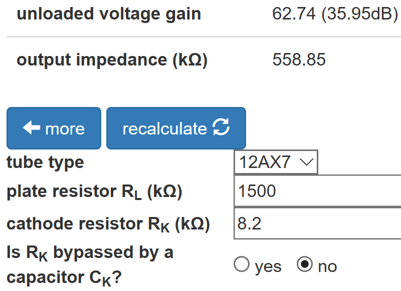
The extremely large plate load resistor increases gain while the large, unbypassed cathode resistor reduces it. Ampeg's strategy is to establish a low DC plate voltage while getting the same gain and neutral bias of a traditional preamp stage. For the same DC grid bias and a traditional 100kΩ plate load resistor, the DC plate voltage would be 100V higher.
By lowering the plate voltage, Ampeg facilitates DC coupling to the phase inverter - there is no DC-blocking coupling capacitor between the two triodes.

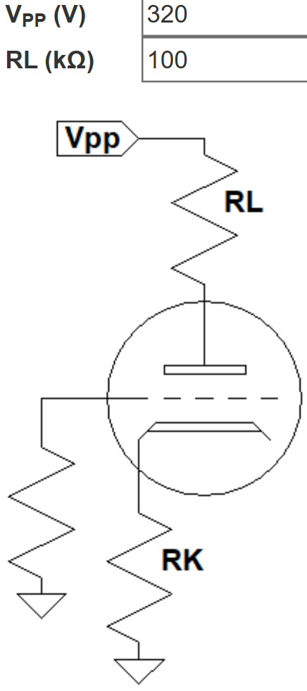
The plate supply voltage for the phase inverter is 320V and there is a total of 300kΩ resistance in series with the tube, so if the plate-to-cathode voltage is 0V, the plate current is
320V / 300kΩ = 1.07mA
The DC load line, shown here in red, is therefore defined by 320V and 1.07mA.
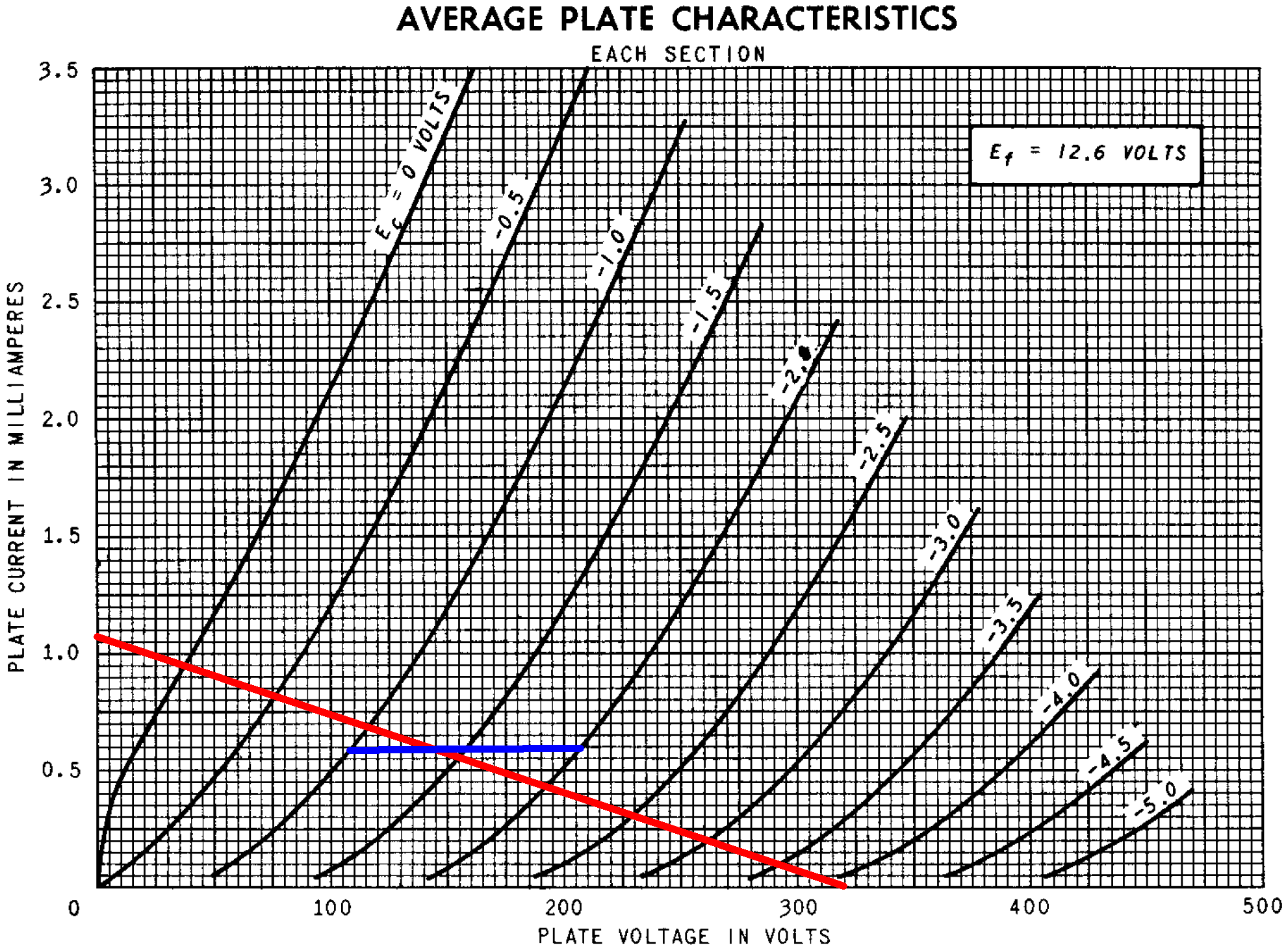
If the grid-to-cathode voltage is -1V, then the cathode-to-ground voltage is 88V. According to Ohm's Law, the plate current is
88V / 150kΩ = 0.587mA
For grid-to-cathode voltages of -1.5V and -2V, the corresponding plate current values are 0.59mA and 0.593mA, respectively. These points define the blue line segments.
The red and blue lines intersect at a fairly neutral DC grid bias of -1.4V.
For the grid-to-cathode voltage to swing from -1.4V to 0V, the plate current swings from 0.59mA to 0.94mA. To compensate for cathode degeneration,4 the grid-to-ground voltage, which is the input signal, needs to swing by 1.4V plus an additional
(0.94mA - 0.59mA)(150kΩ) = 53V
Input headroom is therefore about 54V, much greater than power amp headroom. According to the DC load line, output plate voltage swing is almost 300V, which is split between the two outputs for a swing of almost 150V. This neglects the 270kΩ AC loads of the power amp grid stoppers, which create an AC load line that is rotated slightly clockwise around the DC operating point.
Clearly, however, the AC swing is much greater than needed to drive the power amp to full power. The power amp's input headroom is only 13V peak based on its DC grid bias, so the power amp is in overdrive long before the phase inverter reaches its limits of voltage swing.
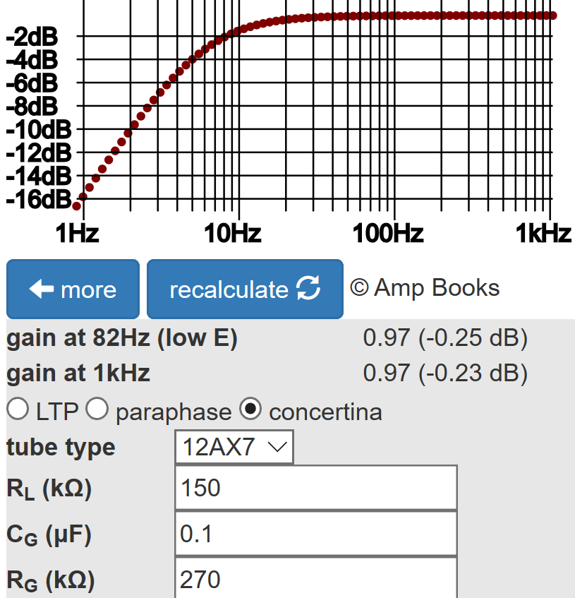
According to the Phase Inverter Bass Response calculator, there is no significant bass attenuation in the coupling circuit.
This is an amp designed to operate all the way up to full power without the triodes contributing significantly to the amp's distortion dynamics.5 Distortion is almost entirely characterized by the qualities of the 7591 power tubes, which Aspen Pittman has described as "a very clear, even tone, and smooth, soft distortion."6
References
1Dave Hunter, Amped, (Minneapolis: Voyageur Press, 2012), p. 62-63.
2Richard Kuehnel, Guitar Amplifier Electronics: Basic Theory, (Seattle: Amp Books, 2018), pp. 43-50.
3Richard Kuehnel, Guitar Amplifier Electronics: Basic Theory, (Seattle: Amp Books, 2018), pp. 130-134.
4Richard Kuehnel, Guitar Amplifier Electronics: Basic Theory, (Seattle: Amp Books, 2018), p. 61.
5Richard Kuehnel, Fundamentals of Guitar Amplifier System Design, (Seattle: Amp Books, 2019).
6Aspen Pittman, The Tube Amp Book, Deluxe Revised Edition, (San Francisco: Backbeat Books, 2003), p. 115.


