Grid Bias Excursion Calculator
 Launch me!
What does this calculator do?
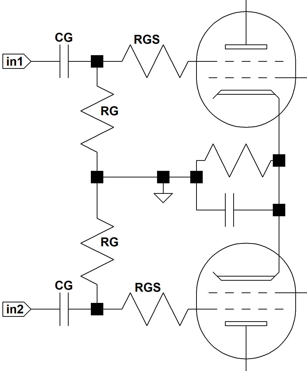
In a guitar amplifier a coupling capacitor CG connects a preamp or phase inverter to the power amp. The capacitor effectively isolates the high DC voltage in the driving stage from the DC grid bias of the power stage. Audio signals pass through the capacitor but DC is blocked.
Put a different way, the voltage across the capacitor normally averages out to the difference between the DC plate voltage of the driving stage and the DC grid voltage of the power amp. Over the course of one cycle of an audio signal, the capacitor voltage doesn't appreciably change and thus the DC difference it represents doesn't appreciably change. The voltage at the capacitor output is equal to the voltage at its input minus the DC voltage across it. The output waveform is thus identical to the input waveform minus the DC voltage drop.
This coupling method has unique consequences when the power amp is overdriven to the point where the power tube grid conducts significant current. As the voltage at the input side of the capacitor increases further, the voltage at the output side is dragged down by the grid, which refuses to rise above the cathode voltage by any appreciable amount. The resulting current that develops through RGS quickly charges the capacitor, increasing the voltage across it. This is a process known as clamping.
The higher voltage across the capacitor increases the effective DC grid bias of the power stage. A Class AB amplifier, for example, effectively begins to operate closer to Class B. This is the essence of bias excursion.
When the input signal amplitude is finally reduced, the excess voltage across the capacitor bleeds off slowly through the grid resistor RG in a process known as bias recovery. Bias excursion and recovery are important characteristics of a guitar amplifier's transition to and from an overdriven state.
To quantify the dynamics of overdriving a guitar amplifier we can use three measures: the bias excursion ratio, the bias excursion time, and the bias recovery time.1 The bias excursion ratio, which has a minimum of zero and a maximum of one, is a measure of how much the grid bias voltage ultimately changes when the power amp is overdriven long enough for the coupling capacitor CG to fully clamp due to grid current. Bias excursion time characterizes how quickly the effective grid bias changes when the power tubes are overdriven. Bias recovery time measures how quickly the bias recovers from an overdriven state.
The excursion ratio is dependent only upon the resistor values in the grid circuit. The excursion and recovery times are also dependent on the value of the coupling capacitor CG. Reducing the size of the coupling capacitor causes the grid bias to recover more quickly, but it also reduces bass response by introducing more reactance into the circuit at low frequencies.
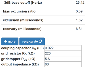
The calculator computes the -3dB bass cutoff frequency, the bias excursion ratio, the bias excursion time in milliseconds, and the bias recovery time in milliseconds. The calculations focus on the clamping action of the coupling capacitor CG due to grid current, so they assume that the cathode bias voltage or fixed bias supply voltage remain constant. In reality these are not perfect voltage sources.


