Designing a Preamp with Parallel Triodes
Matchless, TopHat, Mojave, ...
In the course of guitar amp design it is not uncommon to achieve system objectives with an odd number of triodes. This can create a dilemma, because triodes like the 12AX7 come in pairs. What do we do with the extra triode? Fender's decision for the Blues Deville was to leave it unused. For the Hot Rod Deville, on the other hand, Fender opted to insert the extra triode into the signal path for extreme gain.
Another option is to put two triodes in parallel, like in the Matchless Chieftan, TopHat Club Deluxe, or Mojave Coyote.
Victor Mason at Mojave Ampworks believes putting triodes in parallel is one of the secrets of the Coyote's design:
The biggest secret is that we use the dual triode of the 12AX7s in parallel. It's an application that has been widely used in the hi-fi world, and that was what we brought to the table for guitar amps. It rejects noise better ... and it increases the current output from the tube device. It behaves a little better overall.1
Let's examine the effects of this technique and create a preamp stage with parallel triodes.

|
Guitar Amplifier Electronics: Fender Deluxe - from TV front to narrow panel to brownface to blackface Reverb |
Parallel Triode Characteristics
Under typical small-signal conditions, a single 12AX7 triode has an amplification factor of μ = 100 and a transconductance of about gm = 1.6 millisiemens. The plate resistance is
rp = μ/gm = 62.5kΩ
Interelectrode capacitances are 1.6pF grid-to-cathode, 1.7pF plate-to-grid, and 0.4pF plate-to-cathode. With these parameters, an AC model can be built based on a voltage dependent current source.2
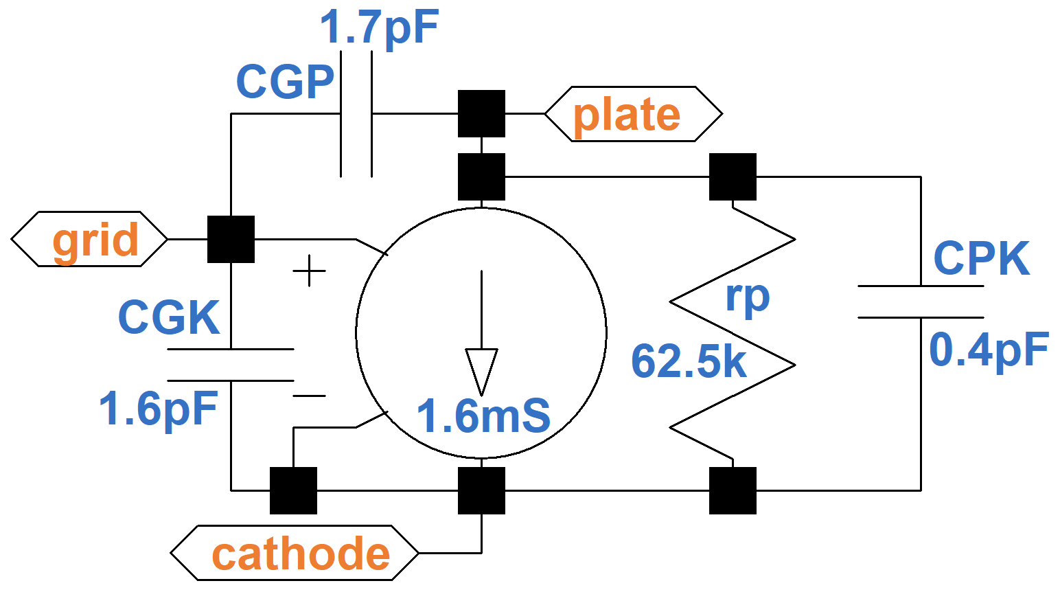
Based on the transconductance, if the grid-to-cathode voltage increases by, say, 1 millivolt, then the plate-to-cathode current increases by 1.6 microamps.
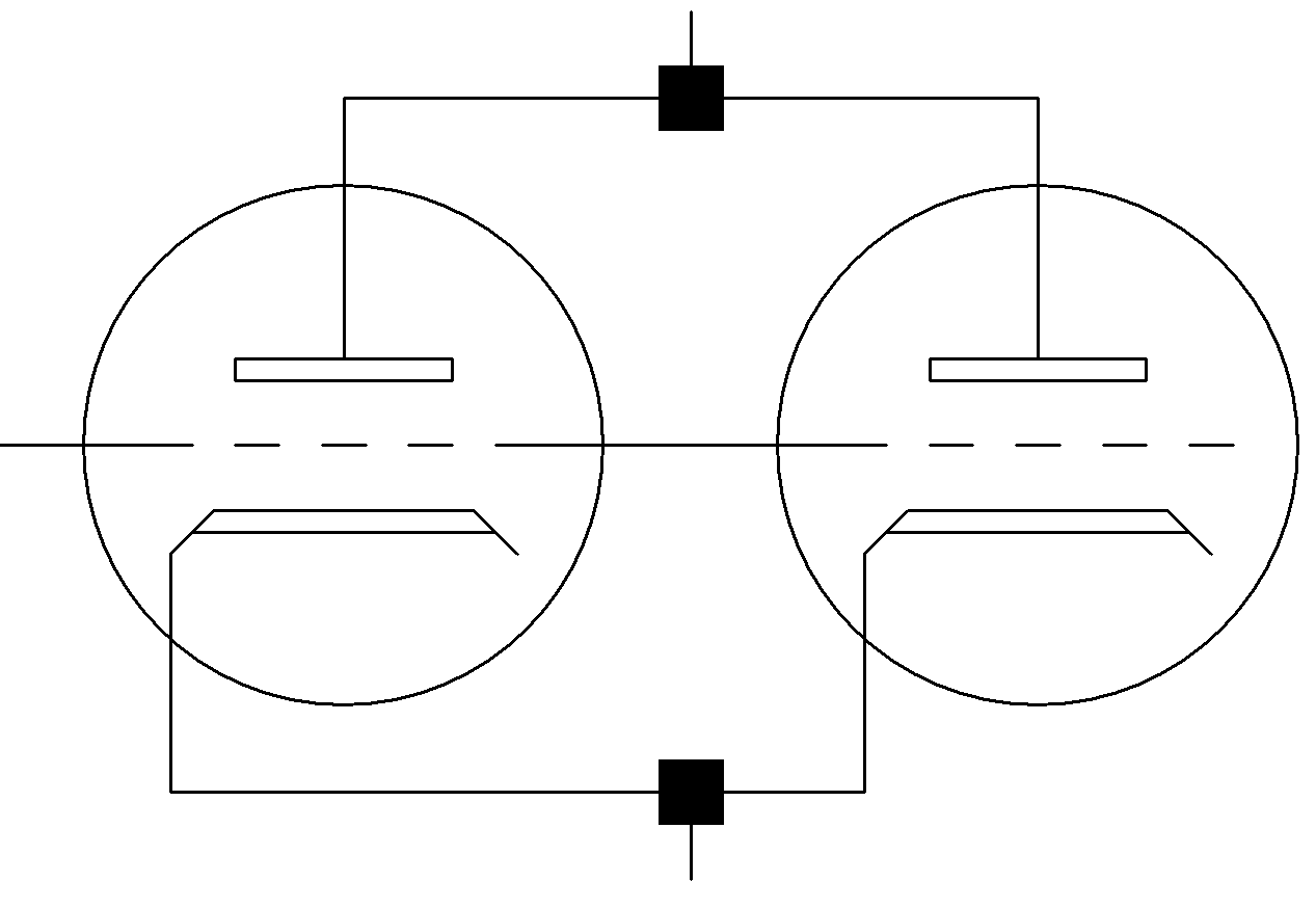
Let's add another triode and connect it plate-to-plate, grid-to-grid, and cathode-to-cathode.
Looking at the two identical circuits in parallel, it is clear that the capacitors, current sources, and plate resistances are in parallel, so the transconductance and capacitances are doubled. The plate resistance is cut in half. This gives us the following equivalent circuit.
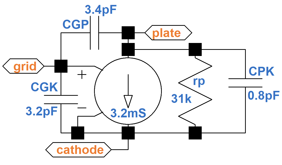
The amplification factor is the product of the transconductance and plate resistance, so if one doubles and the other is halved the result is the same: μ = 100. Each triode can handle 1W plate dissipation, so they combine for a 2W limit. This assumes, however, that the glass tube can withstand the heat stress of two triodes operating at their limits, which is questionable. Rarely do we run preamp plates beyond luke warm, however, so the actual dissipation limit is a moot point.

|
Guitar Amplifier Electronics: Basic Theory - master the basics of preamp, power amp, and power supply design. |
A Preamp Stage with Parallel Triodes
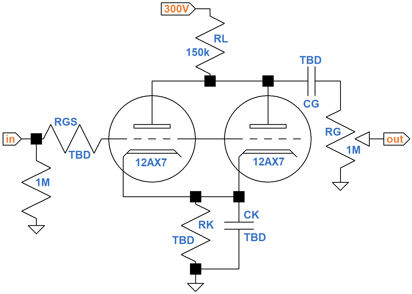
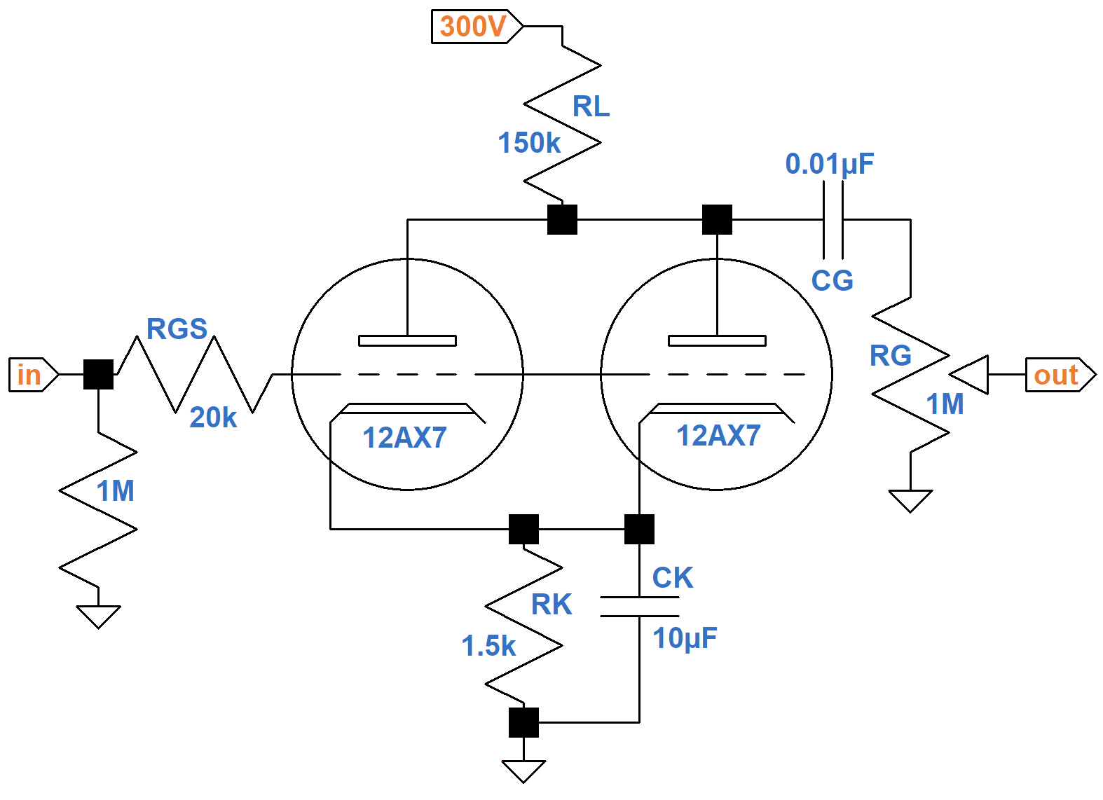
As Victor Mason states, a parallel stage increases the signal-to-noise ratio, which is particularly important in the first stage. Moreover, with the same amplification factor and half the plate resistance we get a bit more gain driving an AC load,3 which is important at the front end to boost the guitar signal well above the noise floor. Let's place the parallel stage between the guitar input jack and a gain control.
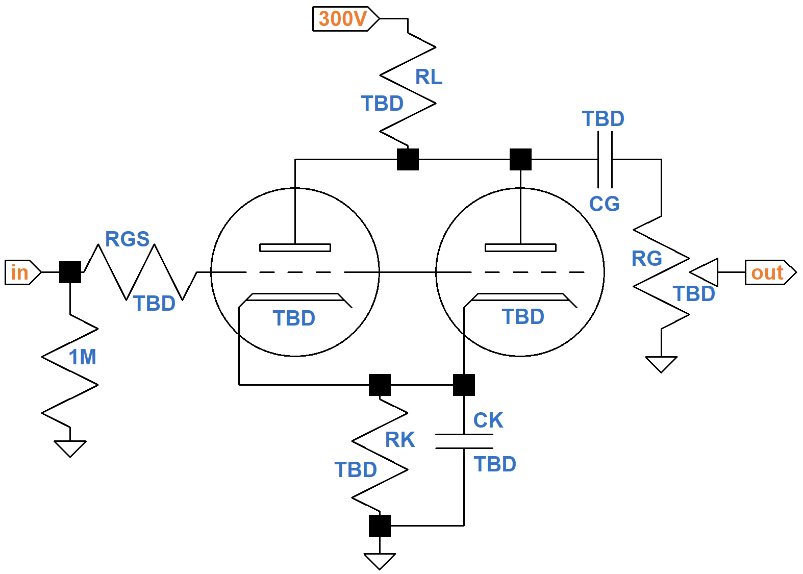
(TBD = "to be determined"). For maximum gain we can use a 12AX7 for both triodes, which is the usual choice. In parallel, they can supply more current to the input of the next stage. Nevertheless, let's load them up lightly by using a 1MΩ gain control. If we set the plate load resistor to 220kΩ as in some Matchless amps, we get the equivalent of 440kΩ for a single triode. The triodes are sucking electrons through a very small straw! This reduces plate current, increases plate resistance, and decreases the amplification factor. Clearly Matchless has proven that 220kΩ works well for RL, but let's use a less aggressive value of 150kΩ.

|
Fundamentals of Guitar Amplifier System Design - design your amp using a structured, professional methodology. |
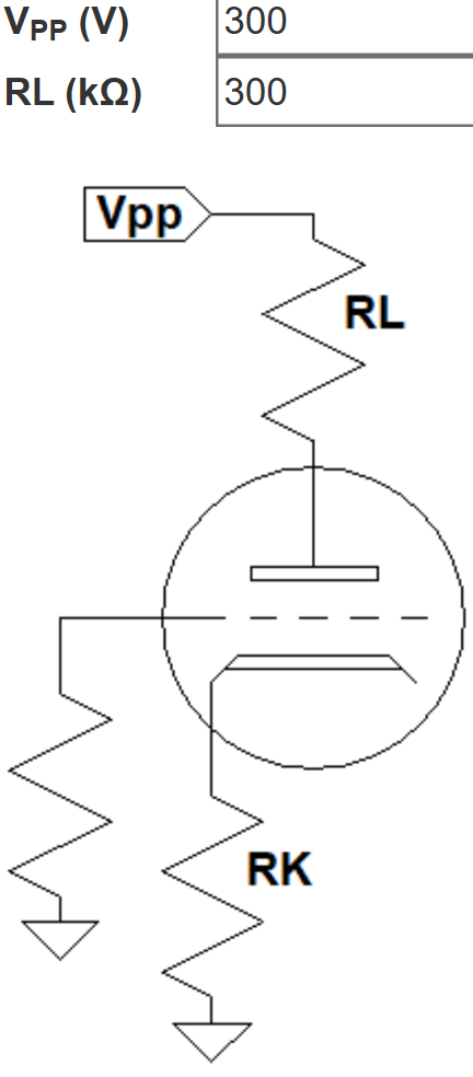
To use the 12AX7 calculator, which is designed for a single triode, we double the plate load resistor value to 300kΩ.
According to the calculator, 3kΩ for cathode resistor RK creates a DC grid bias of -1.5V and an idle plate current of 0.5mA.
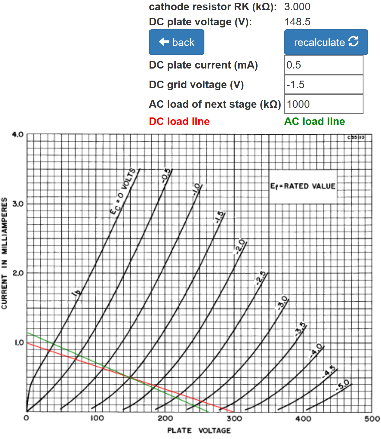
This is for a single triode. For two parallel triodes, the total plate current is 1mA, so the cathode resistor value needs to be cut in half to create the same voltage drop, making the value for RK equal to 1.5kΩ.

|
Guitar Amplifier Electronics: Circuit Simulation - know your design works by measuring performance at every point in the amplifier. |
Let's assume our system's frequency response profile4 calls for very little treble attenuation from RGS and only a slight amount of bass attenuation from CK and CG. To select the appropriate parts values, it helps to know the small-signal parameters at the DC operating point. According to the 12AX7 sheet, for a DC plate voltage of 100V and a DC plate current of 0.5mA per triode, the amplification factor is 100 (red dot) but the plate resistance is 80kΩ, which is higher than we normally assume.
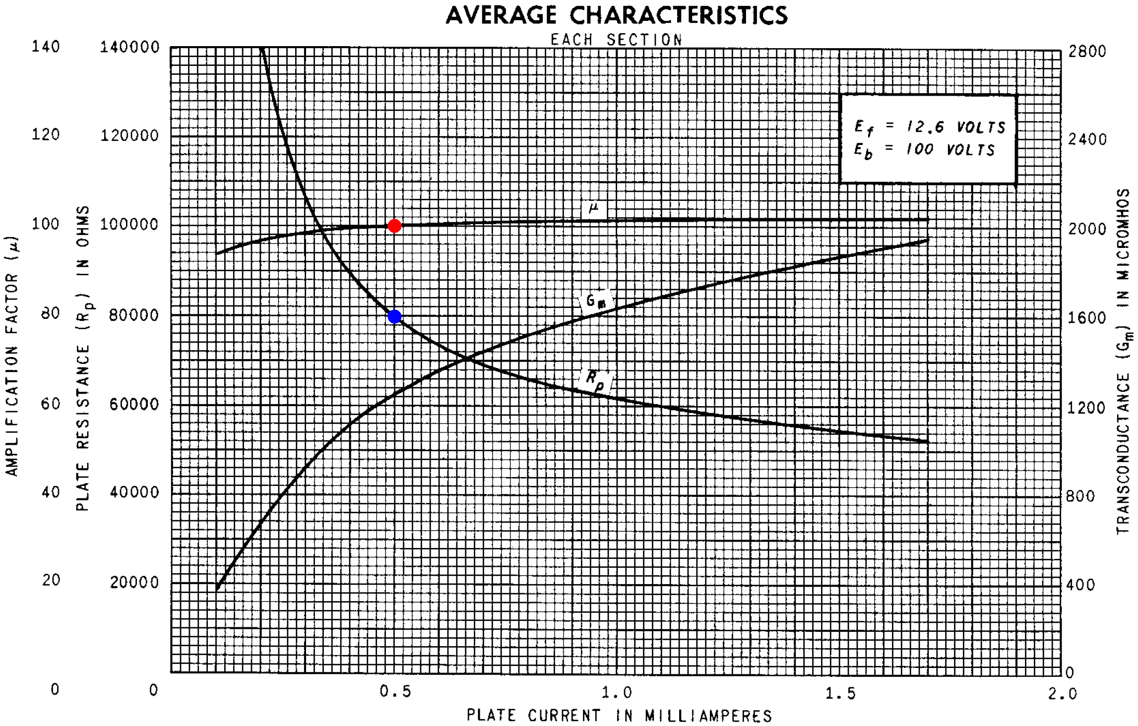
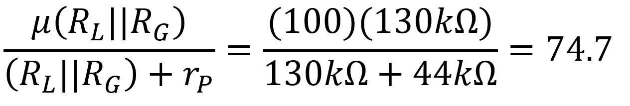
For a DC plate voltage of 250V, the data sheet shows a plate resistance of 101kΩ. For our 150V plate, let's assume 88kΩ, which for two triodes in parallel means rp = 44kΩ. The 150kΩ plate load resistor and 1MΩ volume control in parallel respresent an AC resistance of 130kΩ. This makes the loaded voltage gain, assuming a fully bypassed cathode resistor, equal to
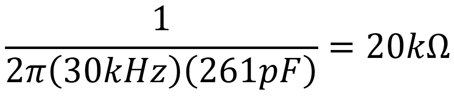
The Miller capacitance between the grids and ground is equal to5

For minimal attenuation at 10kHz, let's select a value for RGS that creates a -3dB cutoff frequency of 30kHz, neglecting the output impedance of the guitar:
The impedance between the cathode and ground is equal to RK in parallel with6
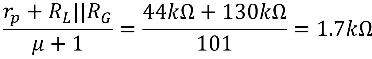
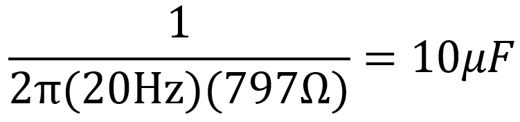
CK is therefore in parallel with 1.5kΩ||1.7kΩ = 797Ω. To set the -3dB cutoff frequency for CK equal to 20Hz, less than the lowest note on a guitar by a factor of 4, its value needs to be
The voltage amplifier's output impedance when the cathode resistor is fully bypassed is equal to the plate load resistor value in parallel with plate resistance:
R0 = RL||rp = (150kΩ)||(44kΩ) = 34kΩ
For a -3dB break frequency of 20Hz, the value of CG is7
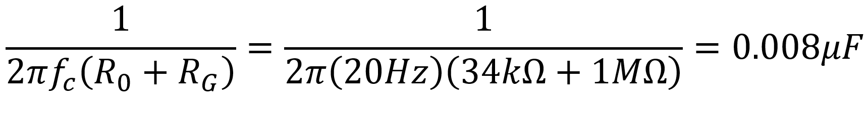
A 0.01μF value works. Here are the final results.
References
1Dave Hunter, The Guitar Amplifier Handbook, (Milwaukee: Backbeat Books, 2015), p. 257.
2Richard Kuehnel, Guitar Amplifier Electronics: Circuit Simulation, (Seattle: Amp Books, 2019), pp. 50-56.
3Richard Kuehnel, Guitar Amplifier Electronics: Basic Theory, (Seattle: Amp Books, 2018), p. 67.
4Richard Kuehnel, Fundamentals of Guitar Amplifier System Design, (Seattle: Amp Books, 2019), p. 114.
5Richard Kuehnel, Guitar Amplifier Electronics: Basic Theory, (Seattle: Amp Books, 2018), p. 72.
6Richard Kuehnel, Guitar Amplifier Electronics: Basic Theory, (Seattle: Amp Books, 2018), p. 62.
7Richard Kuehnel, Guitar Amplifier Electronics: Basic Theory, (Seattle: Amp Books, 2018), p. 68.


