Circuit Analysis of the Guild Parallel LTP Phase Inverter
An Unusual Design
Here is something not often seen in a guitar amp: a four-triode phase inverter, as found in the Guild 100-J.
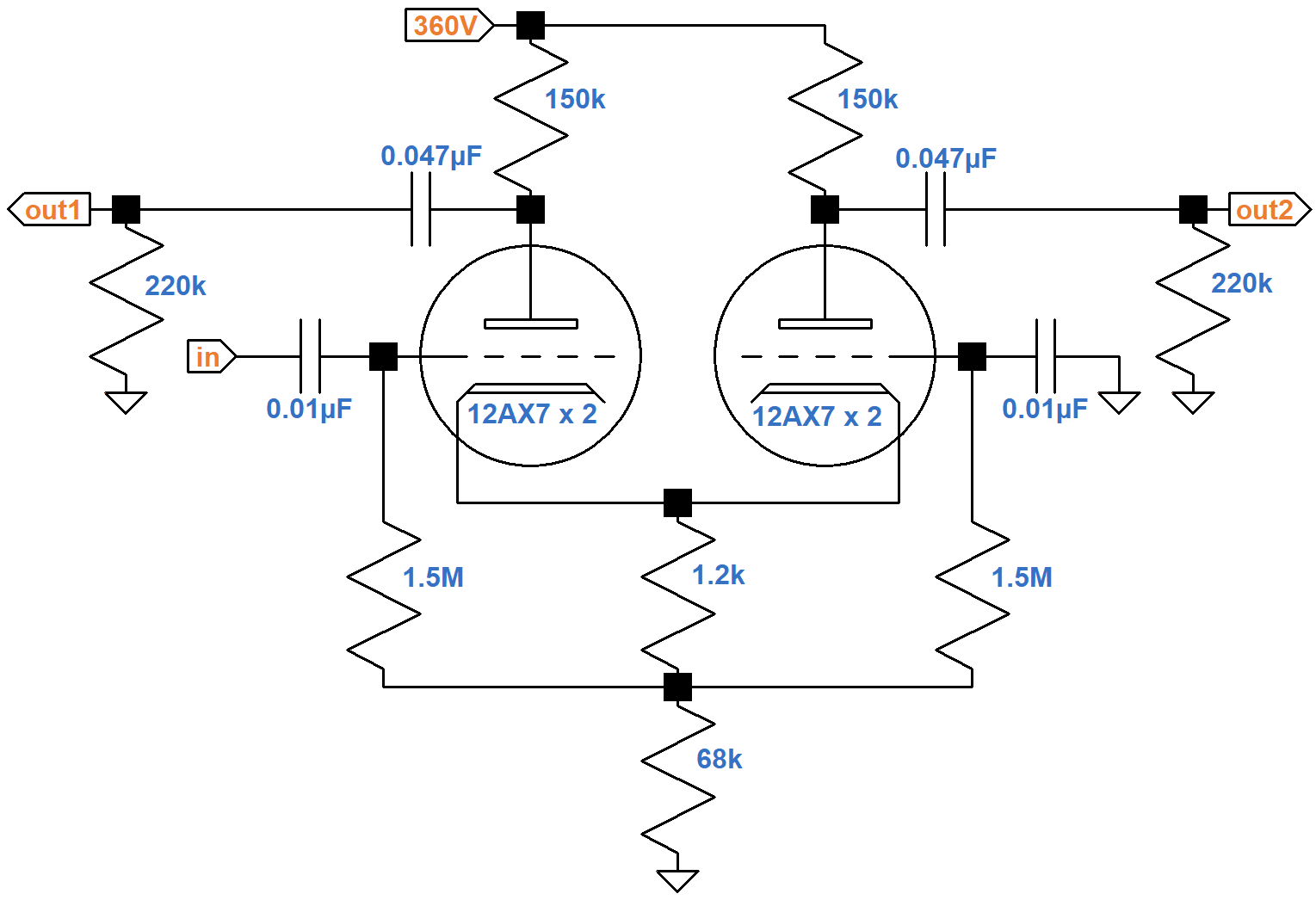
Each of the two triodes shown are actually a pair of triodes in parallel, connected plate-to-plate, grid-to-grid, and cathode-to-cathode.
DC Conditions
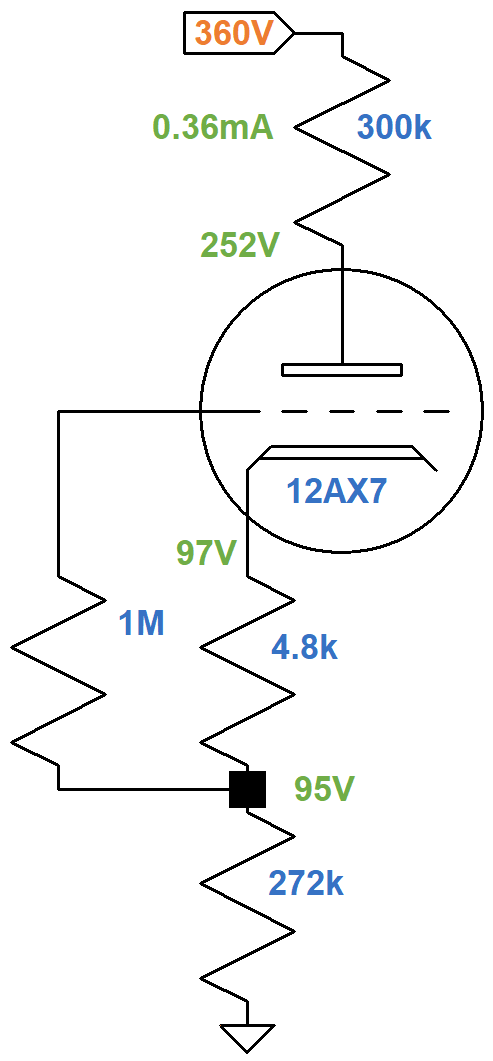
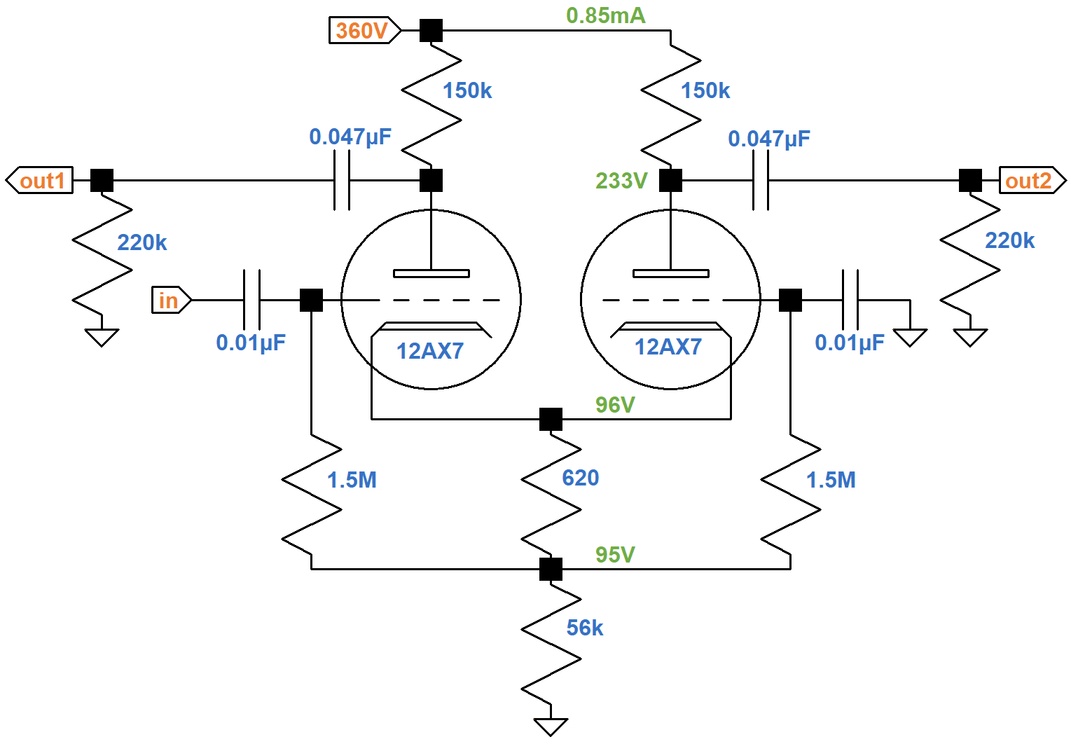
The 150kΩ plate load resistors carry the plate current of two triodes, so the equivalent value for one triode is double: 300kΩ. The 1.2kΩ and 68kΩ resistors carry the plate current of four triodes, so the equivalent value for one triode is quadruple: 4.8kΩ and 272kΩ, respectively. Here is the equivalent DC circuit for one triode.

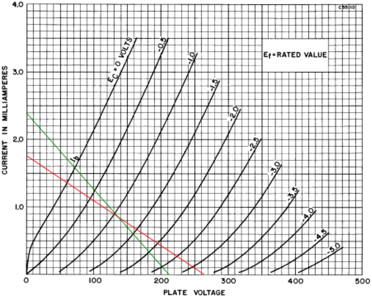
If the plate current is 0mA, the plate-to-cathode voltage is equal to the plate supply voltage, so one endpoint of the DC load line is at 360V, 0mA. If the plate-to-cathode voltage is 0V, then according to Ohm's Law the plate current is
360V / (300kΩ + 4.8kΩ + 272kΩ) = 0.62mA
The other endpoint for the load line is therefore at 0V, 0.62mA, as shown here in red.
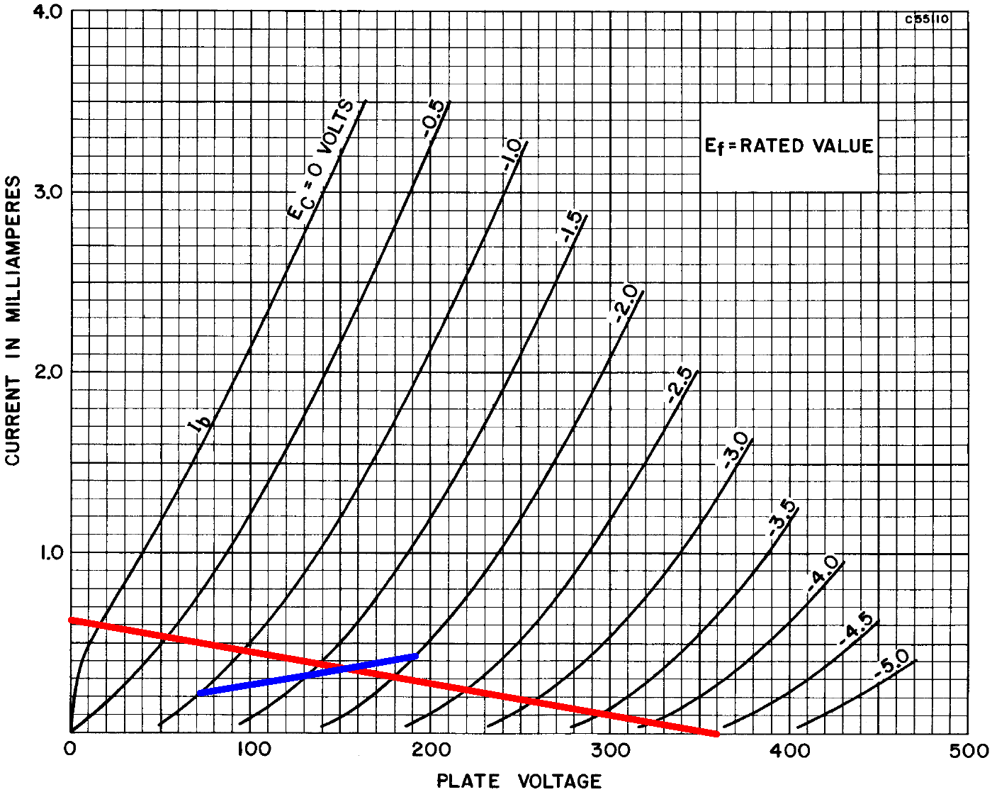
If the grid-to-cathode voltage is -1V, -1.5V, or -2V, then according to Ohm's Law the current through the 4.8kΩ resistor is
-1V / 4.8kΩ = 0.21mA
-1.5V / 4.8kΩ = 0.31mA
-2V / 4.8kΩ = 0.42mA
These points define the blue line segments. They intersect the load line at the DC operating point: -1.7V grid-to-cathode, 155V plate-to-cathode, and 0.36mA plate current. A quick check of Ohm's Law for each of the three resistors validates the voltages shown here, which are for an average 12AX7.
Guild's measured voltages are lower: 220V at the plate and 80V at the cathode.

|
Guitar Amplifier Electronics: Fender Deluxe - from TV front to narrow panel to brownface to blackface Reverb |
In response to an audio signal, when the plate current increases for the inverted phase it decreases for the non-inverted phase, so the 95V across the tail ideally stays constant. The AC plate load is the 150kΩ plate load resistor in parallel with the 220kΩ grid-leak resistor: 89kΩ. This value is doubled to get the equivalent AC load for one tube: 178kΩ. The AC load line has this slope and passes through the DC operating point, as shown here in green.
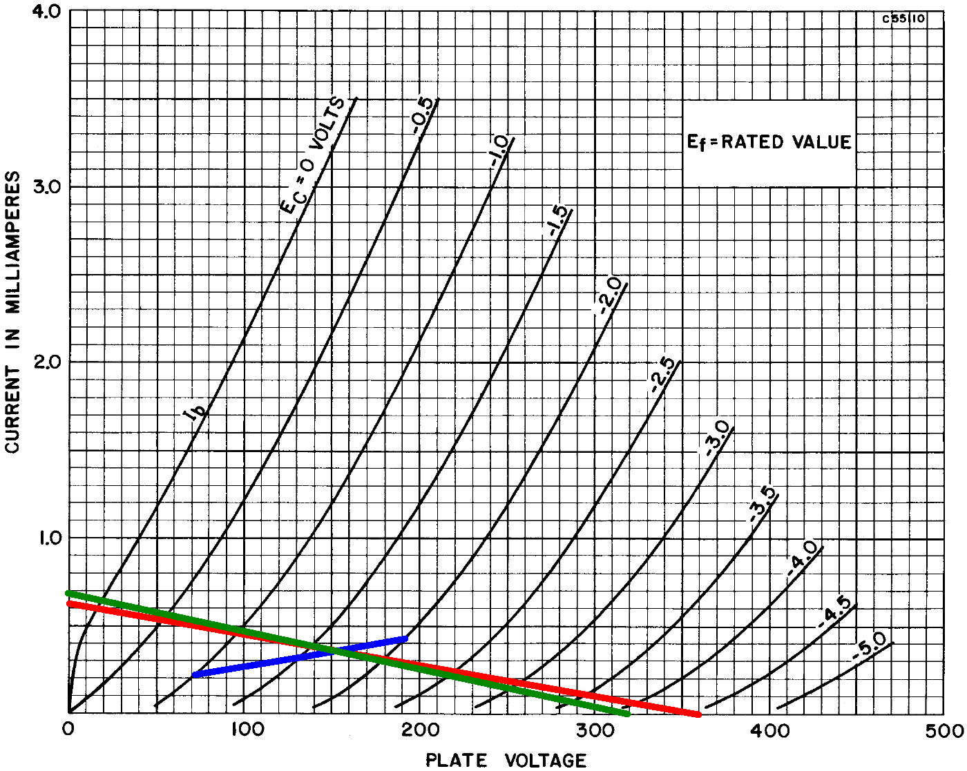
Maximum output voltage swing is from 20V to 319V, representing -135V to +164V relative to 155V at the DC operating point. This is some serious swing! The power tubes will be in overdrive long before these limits are reached.

|
Guitar Amplifier Electronics: Basic Theory - master the basics of preamp, power amp, and power supply design. |
AC Conditions
The gain of the LTP is approximately half the gain of a common cathode voltage amplifier because grid-to-cathode voltage swing is only about half the input grid-to-ground voltage swing.1 Two triodes in parallel are the equivalent of one triode with double the transconductance and half the plate resistance. The amplification factor is the same. For two 12AX7 triodes in parallel and a typical DC operating point, the equivalent single triode has a transconductance gm = 3.2mS, a plate resistance rp = 31kΩ, and an amplication factor μ = 100.
For plate load resistor RL = 150kΩ and grid-leak resistor RG = 220kΩ, the voltage gain when loaded by the grid leak is

The output impedance is
RL||rp = 150kΩ||31kΩ = 26kΩ

|
Fundamentals of Guitar Amplifier System Design - design your amp using a structured, professional methodology. |
Comparison with Conventional LTP Design
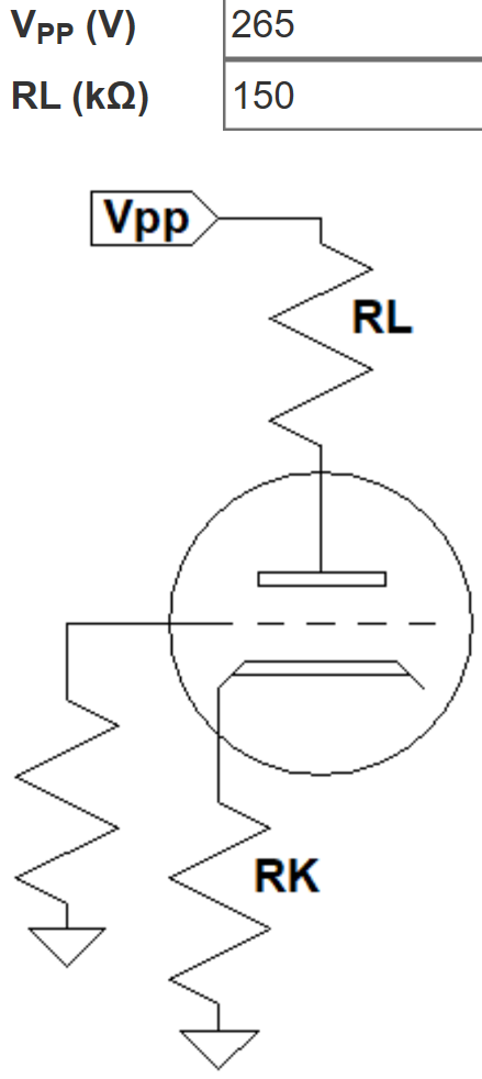
Let's design a traditional 2-triode LTP for the same constraints and compare the results. We assume the plate supply voltage is 360V and the desired voltage across the tail is 95V. The tail voltage is a tradeoff between two performance metrics: a higher tail voltage creates greater balance between phases but less output voltage swing.
The equivalent plate supply voltage for a common cathode voltage amplifier is the voltage difference between the actual plate supply and the tail voltage: 265V. According to the 12AX7 calculator if we set the bias to a warm -1.05V, the cathode resistor value for one triode is 1.235kΩ.
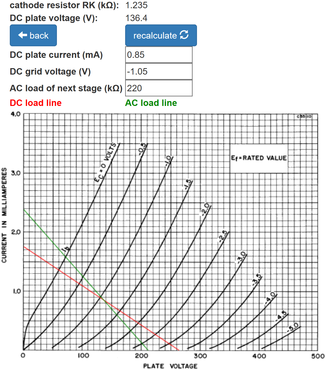
The value for two triodes is half: 620Ω. The DC plate current is 0.85mA for one triode, double for the current through the tail resistor: 1.7mA. According to Ohm's Law, the tail resistor value for a desired voltage drop of 95V is
95V / 1.7mA = 56kΩ

|
Guitar Amplifier Electronics: Circuit Simulation - know your design works by measuring performance at every point in the amplifier. |
Here is our traditional design for a 360V plate supply and a 95V tail.
The green AC load line indicates that maximum output swing is from 71V to 210V, representing -65 to +74 relative to 136V at the DC operating point.
This is quite a bit less swing than for the 4-triode, parallel design. For one triode, the plate resistance is 62kΩ. This makes the voltage gain 29.5 (29.4dB). Output impedance is 44kΩ.
Here is a performance summary.
| Guild 100-J |
Traditional Design |
|
| output, peak-to-peak | 299V | 139V |
| gain | 31dB | 29dB |
| output impedance | 26kΩ | 44kΩ |
The 2dB increase in gain is not worth an extra tube. The pair of triodes can instead be configured as typical voltage amplifiers for a total loaded gain of 71dB.
The decrease in output impedance impacts the dynamics of overdrive, because the Guild design can drive more grid current. Combined with the 100-J's lack of global negative feedback, this should smooth the power amp's transition into overdrive.
The main difference in the two designs, however, is the top line: a substantially greater output voltage swing. Doubling the number of triodes rotates the AC load line counterclockwise to extend the limits of output swing at both ends. The 100-J phase inverter drives a pair of 6L6 power tubes cathode-biased at -33V. The LTP plate voltage needs to swing at least 66V peak-to-peak to drive the power amp to full power. For that, a traditional design using one dual triode is quite sufficient.
References
1Richard Kuehnel, Guitar Amplifier Electronics: Basic Theory, (Seattle: Amp Books, 2018), p. 139.
2Richard Kuehnel, Fundamentals of Guitar Amplifier System Design, (Seattle: Amp Books, 2019), pp. 131-133.
3Richard Kuehnel, Guitar Amplifier Electronics: Circuit Simulation, (Seattle: Amp Books, 2019), pp. 33-37.


