A Battery-Powered Guitar Amp
Traditional guitar amp tubes like the venerable 12AX7 use indirectly-heated cathodes. The heat-producing filament is electrically isolated from the cathode that provides signal-producing electrons. This simplifies the design considerably, because the cathode can be set to a voltage that is completely independent of the heater supply. Battery tubes, on the other hand, use directly-heated cathodes to preserve battery life. By creating its own heat, the cathode of a 1T4 battery pentode, for example, consumes almost 30-times less power than in a 12AX7.
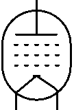
In battery tubes the cathode and heater are the same. This puts significant constraints on the designer, presenting additional challenges not normally found in a guitar amplifier. In this article we will outline some of the basic principles of battery amp design.
How is Cathode Voltage Defined?
The first complication involves the definition of cathode voltage. To create heat, we apply a voltage across a resistance. Thus one end of the filament is at a higher voltage than the other end. If the filament is also acting as the cathode, then its voltage gradually varies from one end to the other. So there are different cathode voltages measured all along its surface.

|
Guitar Amplifier Electronics: Fender Deluxe - from TV front to narrow panel to brownface to blackface Reverb |
This sounds complicated, but tube manufacturers simplify our calculations by referencing all voltages in the data sheet to the minus side of the cathode. When a 1.5-volt battery is placed across the filament to create heat, the cathode voltage is defined as the voltage at the negative end of the battery. All the curves in a data sheet are referenced to this point. If the data sheet refers to a grid voltage of -5V, for example, then the actual grid-to-cathode voltage varies from -5V (measured between the grid and the negative end of the battery) to -6.5V (measured between the grid and the positive end).
Isolated Heaters Mean More Batteries
In a typical guitar amplifier, a single heater supply is routed to all the filaments in parallel. This is not always possible in a battery amp. Cathode followers, concertina phase splitters, and long-tailed-pair phase inverters, for example, have cathodes that float at a voltage much higher than ground. Traditional, single-ended guitar amps have cathode-biased preamps and power amps, which puts the cathodes at positive potentials equal to the desired DC grid bias voltages. You can't connect heaters in parallel without making the cathode voltages the same. Bottom line: the designer has to consider filament heating in the context of cathode DC voltage. Leo Fender and Jim Marshall never faced this challenge, at least in production guitar amps.
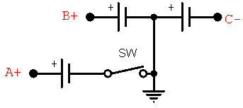
Even if all the cathodes are held at ground potential it is difficult, or at least inefficient, to use a single battery for everything. Generally 3 batteries are required, each having a name derived a century ago, when radios operated off batteries and an AC power supply for consumer electronics was still way into the future.

|
Guitar Amplifier Electronics: Basic Theory - master the basics of preamp, power amp, and power supply design. |
In a typical radio built in 1925, the "A" battery supplied filament heat. This is where most power consumption took place. The battery was physically large and created low voltage and high current. It was usually a lead-acid battery charged every week by the automobile mechanic down the street.
The "B" battery, on the other hand, supplied high voltage and low current to the plates and screens. It lasted a lot longer but was expensive.
Finally the "C" battery set the DC grid voltage. There was never any need for an on-off switch for this battery, because grid current was extremely low while operating and non-existent when the heaters were turned off. The C battery was left continuously connected. Through the years it collected dust and cobwebs and eventually died of old age.
Battery Life and Performance Drift
Voltage gain generally decreases as voltages and currents decrease, and DC voltages vary as the battery ages. Worse things can also happen. Placing the DC operating point close to cutoff using fresh batteries, for example, can create signal clipping as the batteries wear down. The amp needs to be designed for the full range of voltages experienced over the lifetimes of the batteries.

|
Fundamentals of Guitar Amplifier System Design - design your amp using a structured, professional methodology. |
Grid Resistors and DC Bias Voltage
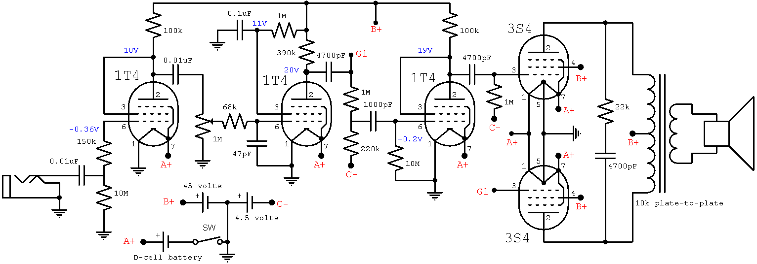
A battery-powered preamp typically uses a large grid resistor, so even a small amount of grid current produces a significant voltage drop across it, creating a DC bias voltage that is less than what is expected. Here, for example, are the DC voltages measured for a triode-connected 1T4 preamp with more than 10 megohms of total grid resistance:
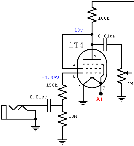
The grid is 0.36V below ground potential because of DC grid current. There is a 1.5-volt battery connected between pins 1 and 7, so the actual DC grid-to-cathode voltage varies from about -0.36V to approximately -1.86V depending on the age of the battery.
It is interesting to note that there is no external cathode resistor, but the cathode itself, as a filament, has substantial resistance and creates bias proportional to heater current. Moreover, the large grid resistor creates additional bias not found in a typical 12AX7 preamp.

|
Guitar Amplifier Electronics: Circuit Simulation - know your design works by measuring performance at every point in the amplifier. |
Oscillation
A guitar amp combines high gain and high bandwidth, so oscillation is always an issue. Coupling capacitors should be large enough to ensure adequate bass response but no more. They tend to be significantly smaller in a battery amp. There are no LC filters or RC filters in the power supply because there is no AC ripple. Moreover, batteries have a low output impedance with excellent regulation, creating a constant DC voltage for a wide range of current demand. This encouraging state of affairs can be deceiving, however. When the entire amplifier, from weak-signal preamp to strong-signal power amp, is driven by the same plate supply, oscillation can easily occur.
A battery amp has fewer components compared to a traditional AC-powered amplifier, offering the opportunity to bring stages closer together in a smaller space. Good layout must be observed, however. In particular, the power amp circuit needs to be kept physically separated from the preamp circuit. Additional preventative measures also may be needed. Here, for example, a 47pF capacitor is placed across the grid of a 1T4 voltage amplifier to provide greater radio-frequency suppression.
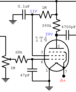
Without it, the parasitic capacitance of the components and wiring would probably exceed the Miller capacitance of the pentode, making RF suppression dependent on the nuances of the layout.
References
Here is a battery-powered amp practice amp using 1T4 preamp stages and a 3S4 power stage in push-pull:
Battery-Powered Tube Amp Schematic
The measured voltages are for our particular tubes and components. Here are data sheets for the 1T4/DF91 and 3S4/DL92:
1T4 datasheet
3S4 datasheet
DF91 datasheet
DL92 datasheet


