Comments on Mesa/Boogie Patent 7,173,488
Mesa/Boogie Duo-ClassTM Power
One of the advantages of a push-pull power amp design, compared to a single-ended circuit, is that the net DC current through the core of the output transformer is zero, assuming the plate circuits are perfectly balanced. This is because the DC currents in the two halves flow in opposite directions, thereby creating opposing magnetic fields that cancel each other.
Reality isn't quite so perfect, especially for Class AB, but to a great extent the core of a push-pull output transformer is only subject to AC signal current.
A single-ended transformer, on the other hand, needs to handle the AC signal superimposed onto a large DC component, which requires special construction techniques to be used to prevent magnetic flux saturation. Push-pull transformers are spared these concerns. Moreover, they can be made significantly smaller for the same output power, which reduces cost, weight, and inter-winding capacitance.
Mesa/Boogie's patent number 7,173,488 describes Duo-ClassTM Power, a technique to enable a push-pull transformer to operate in single-ended mode while maintaining zero net plate current through the transformer core.

|
Guitar Amplifier Electronics: Fender Deluxe - from TV front to narrow panel to brownface to blackface Reverb |
Push-Pull Transformer in Single-Ended Operation
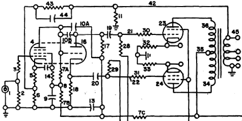
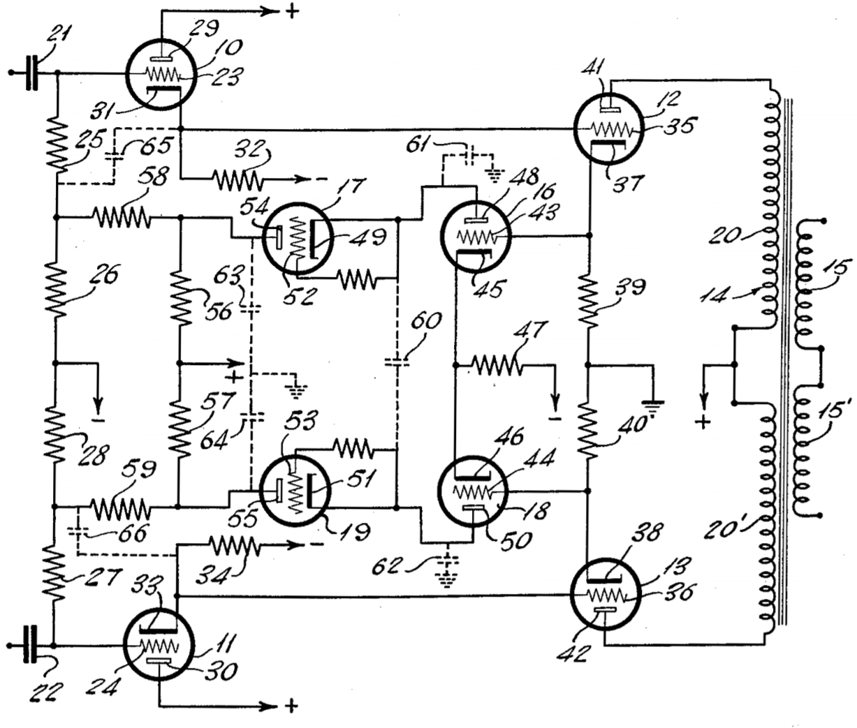
The main feature is a double pole double throw (DPDT) switch or relay.1
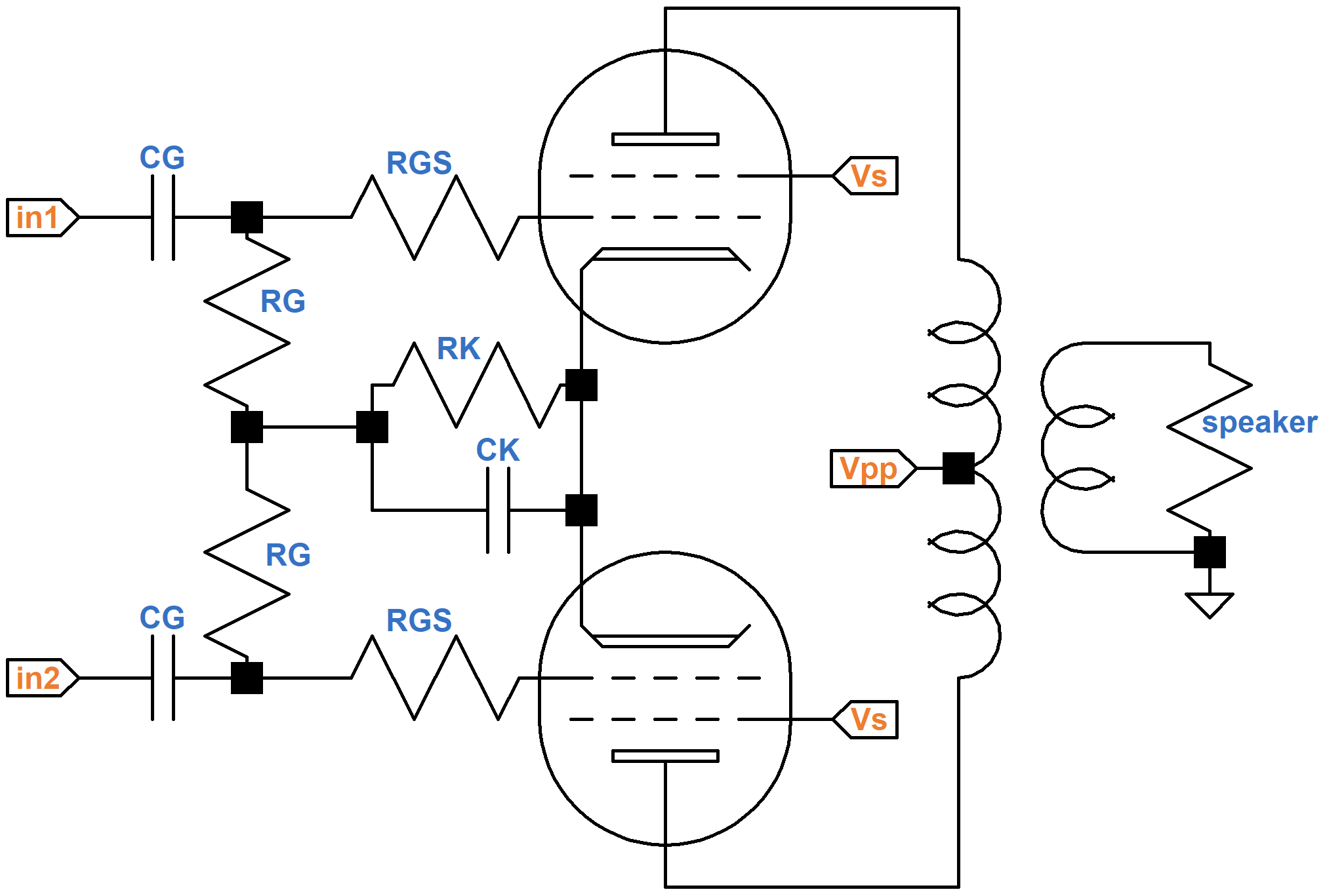
When the switch is thrown to the right, connecting D to F and A to C the circuit operates as a conventional push-pull power amp with cathode bias. The cathode resistor consists of two resistors 19 and 20 in parallel.
The power amp is switched into single-ended operation by shorting the grid circuit of one power tube to ground and decoupling the power tube cathodes. Shorting one grid to ground disconnects the power tube from the phase inverter so that only the upper tube is actively driven by the guitar signal. The cathodes are decoupled to keep the active tube from driving the inactive tube via their connected cathodes.
(If the power amp is fixed bias, then the circuit looks a bit different. Grid resistors 7 and 8 are connected to a negative DC bias supply instead of ground. For single-ended operation, the grid of the inactive power tube is connected to ground via a large capacitor, thereby shorting audio signals while preserving DC grid bias.)

|
Guitar Amplifier Electronics: Basic Theory - master the basics of preamp, power amp, and power supply design. |
When in single-ended mode, the upper power tube operates as a single-ended amplifier with an AC signal superimposed on its DC operating point, as shown here:
The inactive, lower power tube remains at its DC operating point and has no AC component. The net DC current through the transformer core is approximately zero, enabling the push-pull output transformer to operate as a single-ended transformer without suffering from magnetic flux saturation.
Variations
To transform a Class A push-pull amplifier into a Class A single-ended amplifier, resistors 19 and 20 can be equal to twice the desired cathode resistance for push-pull operation. Class AB power tubes, on the other hand, are biased closer to cutoff. Their DC operating points are unsuitable for either the active or inactive phase of single-ended operation. The DC operating points for Class A single-ended and Class AB push-pull operation are substantially different.

|
Fundamentals of Guitar Amplifier System Design - design your amp using a structured, professional methodology. |
One solution is to insert a third resistor in series with 19 and 20 for push-pull. Another, even simpler approach is to create separate cathode circuits for each mode and switch cathodes 17 and 18 between them. This technique also enables a cathode bypass capacitor for Class AB to be conveniently inserted.
Even if push-pull is pure Class A, which doesn't require a cathode bypass capacitor, the active power tube has less voltage gain when operating in single-ended mode. Because of negative feedback caused by cathode degeneration, it takes more guitar signal to drive the single-ended tube to full power.
Because of negative feedback not present in push-pull mode, more guitar signal is required to drive the power amp to full power. The two modes therefore have substantially different input sensitivity. A standard solution is to place a cathode bypass capacitor in parallel with resistor 19. This creates a more constant input sensitivity between the two operating modes. With the capacitor, single-ended mode has substantially less volume, as expected, but it breaks into overdrive with the same amount of pressure on the guitar pick.
An even simpler solution is to allow negative feedback for both modes. This is the approach taken by Walter Key and Eugene Coggins in Audio Amplifier with Improved Stability.2
This eliminates the need for a switch in the cathode circuit. Mesa/Boogie's DPDT switch then becomes just an SPST switch between D and E. The remaining switch shorts audio frequencies at the grid of one power tube to ground when overdrive at lower volume is desired.

|
Guitar Amplifier Electronics: Circuit Simulation - know your design works by measuring performance at every point in the amplifier. |
Mesa/Boogie's shorting of the inactive tube grid to ground places a constant load equal to grid-leak resistor 8 in parallel with grid-stopper resistor 6 across the output of the inactive phase of the phase inverter.
The phase inverter needs to supply more current, especially if the grid stopper is smaller than the grid leak, which is usually the case. This differs from normal push-pull operation, where the phase inverter experiences a demanding load only in overdrive as it attempts to drive a power tube grid positive.
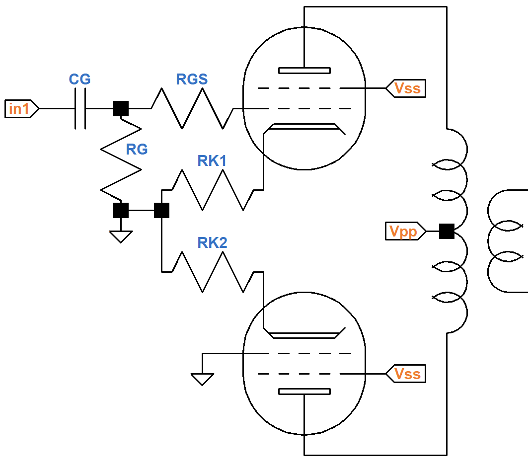
A possible solution is to modify the switch circuit as shown here:
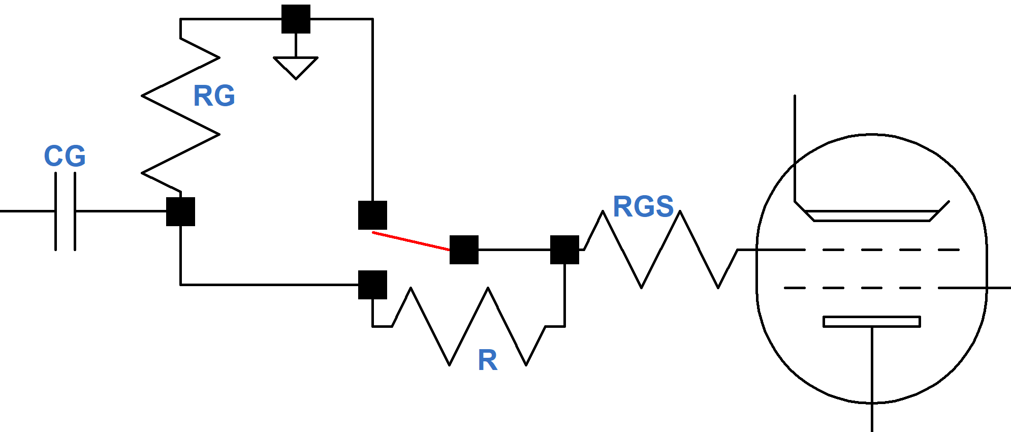
In this design RGS is shifted to the opposite side of the switch. An additional resistor R, which is at least as large as the grid-leak resistor RG, substantially increases the phase inverter load resistance. It also maintains grid leak during the split second when the switch is moving from one position to the other.
The total resistance between the tube grid and ground should not exceed the maximum allowable grid circuit resistance for the power tube. For cathode bias, here are the maximum resistance values for popular power tubes.
EL84 1MΩ 6V6 500kΩ EL34 700kΩ 6L6 500kΩ KT66 500kΩ KT77 500kΩ KT88 270kΩ 6550 250kΩ
Finally, transformer primary impedance should be considered. The desired plate-to-plate impedance for an efficient push-pull amp may not create the desired power level and harmonic content when switched to single-ended mode. Modifications to the primary or secondary circuit to tweak the two operating modes may be required. Even with careful impedance selection we can't expect a push-pull Fender Deluxe 5E3 to sound like a Champ 5E1 when switched to single-ended operation. Nevertheless, the possibilities for two uniquely appealing amplifiers playing through a single transformer is quite an accomplishment.
An Alternative Technique
Mesa/Boogie's patent selects push-pull or single-ended mode with a single switch, but what if we wanted a continuous range of operation between the two extremes? What if we wanted to replace the on-off switch with a master volume control capable of continuously adjusting between push-pull at one extreme and single-ended operation at the other? Martin Kiebert's Self-Balancing Amplifier3 shows one possible implementation.
His approach replaces Mesa/Boogie's SPST grid-circuit switch with two cascode circuits that detect the amount of DC current imbalance in the output transformer and adjust power tube bias accordingly via a pair of cathode followers. Kiebert eliminates magnetic flux saturation dynamically, based on the actual balance between the power tubes. His design anticipates that power pentodes may not be well matched and provides overall bias adjustment in response to varying tube transconductance. To use this plug-and-play approach, all that is needed is to attenuate the audio signal at capacitor 22 with a potentiometer. At maximum we create "self-balancing" push-pull. At minimum we effectively short the audio for one phase.
Kiebert easily could have envisioned that shorting the grid of one tube to ground would force a push-pull amplifier into single-ended operation. He also would have well understood that this results in an increase in harmonic distortion and a lowering of maximum power output. What would have been very difficult for him to imagine, however, is that someone would find this particular application useful. Imagine paying more for a switchable option to increase distortion at lower volume levels. Guitar amplification has turned system design on its head!
References
Here are the original patent documents:


