Comments on Peavey Electronics Patent 7,145,392
Guitar Amp with Variable Harmonic Distortion
Power amps create harmonic distortion because of differences in amplification when operating in different regions of their characteristic curves. Single-ended amplifiers like the one shown here, generally create generous quantities of second harmonic distortion.
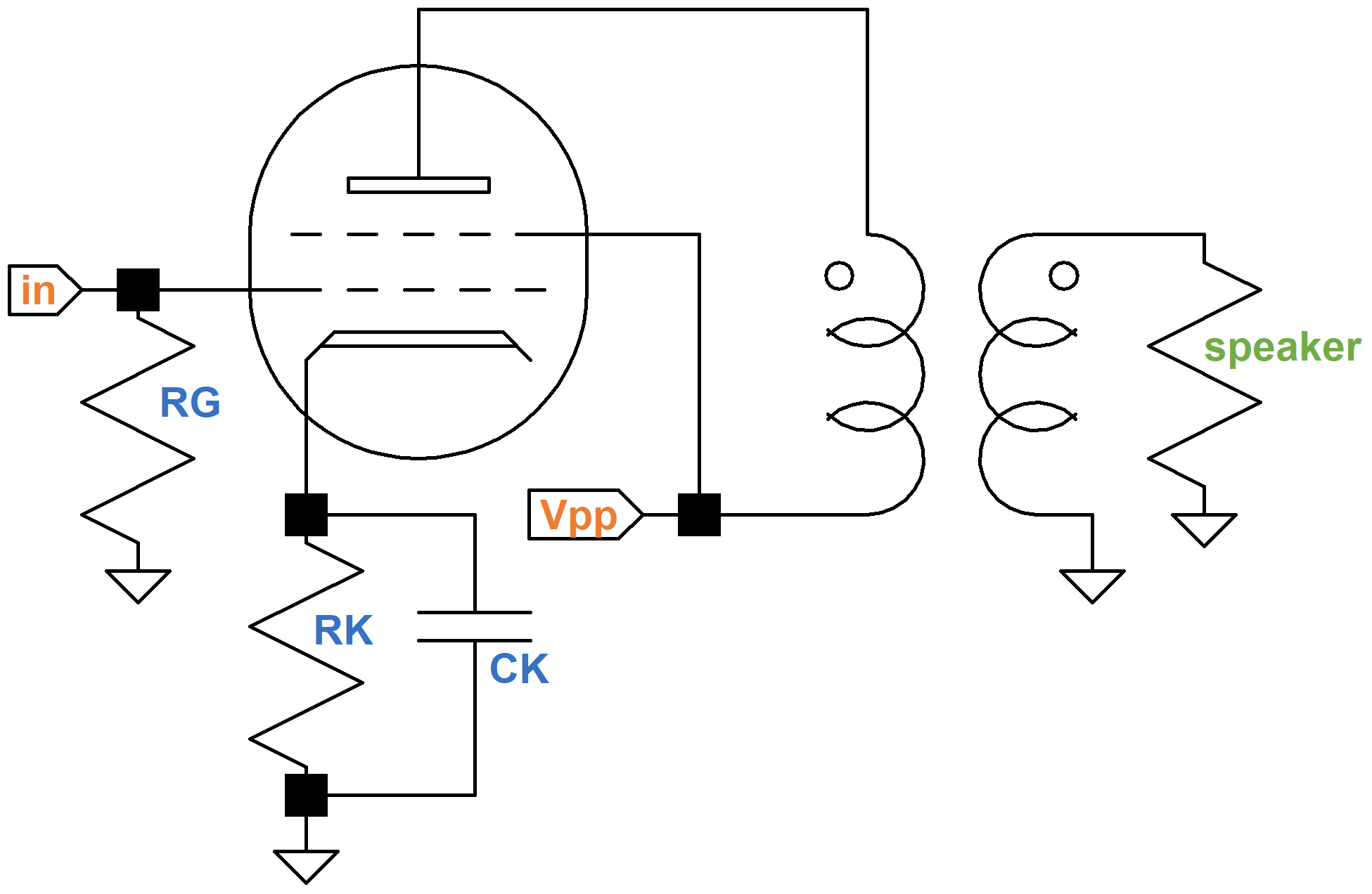
The harmonic mix varies considerably depending on the DC operating point and the output transformer primary impedance, as can be seen in this example using a single-ended 6550 power pentode.
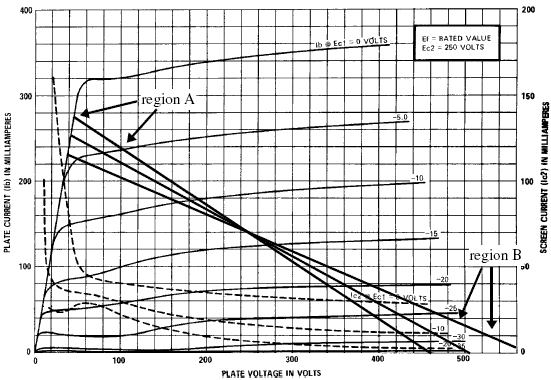
The three load lines correspond to three different transformer output impedances that pivot around the same DC operating point. For the lowest impedance, corresponding to the load line that is pivoted the most clockwise, the grid-voltage curves are further apart in region A compared to region B. This creates second-harmonic distortion because the upper and lower regions are not symmetrical - there is more amplification as the input signal swings positive.

|
Guitar Amplifier Electronics: Fender Deluxe - from TV front to narrow panel to brownface to blackface Reverb |
The highest impedance, corresponding to the load line that is pivoted the most counter-clockwise, also creates second harmonic distortion but for the opposite reason: the grid-voltage curves are further apart in region B compared to region A.
The curves for the middle load line are further apart in the center than they are at the extremes, so there is more amplification as the signal passes through zero than when at positive or negative extremes. This symmetry creates third harmonic distortion.
All three load lines assume that the loudspeaker is a pure resistance that matches the output transformer secondary impedance. In reality, however, speakers are highly reactive and their impedance varies substantially with frequency. This transforms a straight load line into a wildly pivoting montage of ellipses at a variety of slopes. So even when we choose a load line similar to the middle line in the 6550 example, our single-ended power amp will unavoidably produce significant second harmonic distortion at full power.

|
Guitar Amplifier Electronics: Basic Theory - master the basics of preamp, power amp, and power supply design. |
Push-Pull Power Amp Distortion
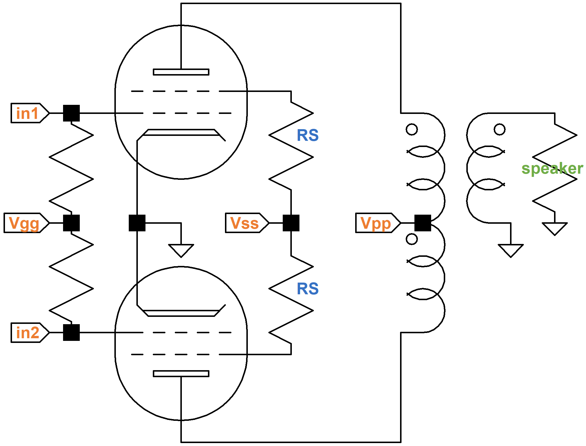
A push-pull amplifier is symmetrical by design, because the circuit driving one phase, including its power tube, is the mirror image of the circuit for the opposite phase.
Purposely designing an amplifier for high-distortion was an unthinkable consumer application back in the hey-day of vacuum-tube technology. Back then the mechanisms of distortion were understood and conquered for the purposes of achieving high-fidelity musical accuracy. So historically the reduction or elimination of second-harmonic distortion was cited as one of the most important "advantages" of push-pull operation.
"There is less distortion for a given power output per tube, or more power output per tube for a given distortion, as a result of cancellation of all even harmonics and even-order combination frequencies."2
Almost any electronics book published during the vacuum-tube era reflected this sentiment.3,4,5,6 Moreover, it has been known for decades that the "advantages" of push-pull are achieved only if the input signal to the power amp is balanced. An imbalance in input signal voltage, where one phase has a higher amplitude than the other, causes even-harmonic distortion to increase, as Langford-Smith stated back in 1953:
"For best results the input voltage must be exactly balanced, the valves must have identical characteristics and the output transformer must be exactly balanced between the two section of the primary, with perfect coupling between them. Under these conditions, any even harmonics introduced by the valves will be canceled, but the odd harmonics will not be affected."7
Langford-Smith also emphasized the importance of balance for Class AB1 power pentode circuits, which populate the overwhelming majority of guitar amplifiers manufactured today:
"The advantages of push-pull operation will only be obtained in proportion to the care taken to achieve correct balance, particularly with regard to the quiescent plate currents and the signal input voltages. As with triodes, Class AB1 is more sensitive to mismatching than Class A1."8
In this historical context, US patent number 7,145,392 describes a technique to control the balance of the input signal, thereby controlling the harmonic content of the power amp. The inventors are Hartley Peavey and John Fields and the patent was assigned to Peavey Electronics Corporation on December 5, 2006. Let's take a closer look.

|
Fundamentals of Guitar Amplifier System Design - design your amp using a structured, professional methodology. |
Attenuating One Phase
As a prelude to his description of a self-balancing paraphase phase inverter9 Langford-Smith notes that a conventional paraphase "is not self balancing, and requires individual adjustment for accurate balance both during manufacture and after the valve has been replaced." His recommendation, however, that the power amp input signals be deliberately and variably controlled to balance the drive and maximize symmetry in the output waveform is not often adopted by present-day guitar amplifier manufacturers. Peavey's patent document, on the other hand, shows precisely this kind of circuit:
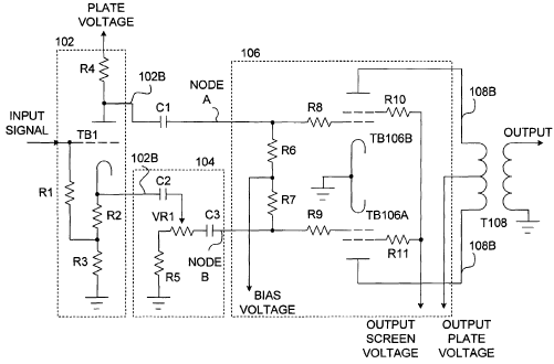
Peavey's adjustment mechanism consists of a simple volume control comprised of R5 and VR1. When the potentiometer is set to maximum the signal for the non-inverted phase is approximately the same as for the inverted phase and the power amp is close to being balanced. At minimum the non-inverted signal is substantially attenuated, resulting in the most imbalance and maximum even harmonic distortion.
Splitting a potentiometer into fixed and variable resistors is a technique used in many applications when the possibility of setting the resistance to zero is undesired. In the DC grid bias supply of the Marshall JMP50 Model 1987, for example, a 72k potentiometer is split into a 47k fixed resistor and a 25k potentiometer:
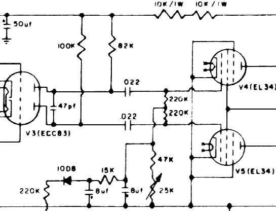
This limits the adjustment range to a maximum of 72k and a minimum of 47k.
Peavey's coupling capacitor C3 is required to block the DC grid bias voltage being supplied via R7. The capacitor serves the same function as C1 and C2 and the 0.022uF capacitors in Marshall's circuit - it blocks DC voltage but allows audio signals to pass.

|
Guitar Amplifier Electronics: Circuit Simulation - know your design works by measuring performance at every point in the amplifier. |
Implementing Peavey's Circuit
The patent claims that "numerous modifications" and "other arrangements" are within the spirit and scope of the invention. This claim is typical in patent documents. Some variations become obvious when we attempt to implement the circuit.
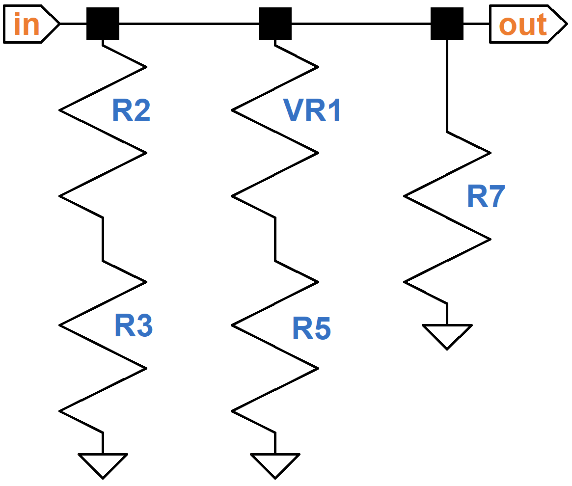
The patent is focused on a very particular application: conventional, balanced push-pull behavior at one control setting, increased distortion at other settings. Creating balance with the volume control set to maximum is a logical design choice, although the opposite situation could also be implemented. For balance, the concertina phase splitter, as shown in the patent document, needs the same AC load in its plate and cathode circuits.10 Here is the plate load for midrange audio signals, where the coupling capacitor C1 acts as a short circuit:
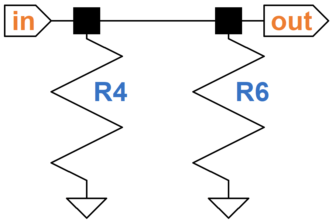
The cathode circuit, assuming the coupling capacitors also act as short circuits for midrange audio, looks like this:
For balance the effective resistance for each signal path needs to be the same. Since resistors are very inexpensive, a computationally simple approach is make both signal paths identical to Peavey's lower circuit. Then the same resistor values appear the inverted signal path:
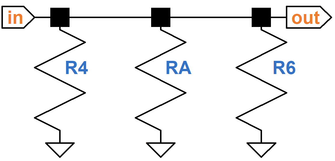
By direct comparison, the resistor values (all fixed) are
R4 = R2 + R3
RA = VR1 + R5
R6 = R7
This topology has the advantage of allowing us to insert a copy of capacitor C3 into the upper circuit, thereby ensuring that attenuation and phase shift are identical in both phases at low frequencies when capacitor reactance becomes significant. (Throwing a balanced circuit into imbalance is easy. Maintaining balance over all frequencies is much more challenging, especially if the circuits are not symmetrical.)
If, on the other hand, we insist on implementing the circuit exactly as depicted in the patent document, then balance is achieved when
R4 || R6 = (R2 + R2) || (VR1 + R5) || R7
These computations assume that the coupling capacitors are large enough to act as short circuits at guitar signal frequencies. In determining their minimum values we obtain sufficiently accurate results when we assume that two of the three coupling capacitors are short circuits and then compute the third capacitor's minimum value for a desired bass response. Let's begin by shorting C1 and C3. The concertina's output impedance driving the power amp's non-inverted phase, is
ZoT = (R2 + R3) || [(ZL+rp) / (mu + 1)]
where the AC plate load is
ZL = R4 || R6
and the variables mu and rp represent the triode's amplification factor and plate resistance, respectively. The value of C2 needed to achieve a -3dB bass cutoff frequency F is
C2 = 1.0 / sqrt{ (2) (pi) (F) (ZoT + [(R5 + VR1) || R7]) }
Guitar amplifier designers typically set the -3dB cutoff frequency to well below 82 Hertz, the lowest note on a guitar with standard tuning. The Marshall JMP50 Model 1987, for example, is designed for a cutoff of 25 Hertz.
Similarly, the value of C3 needed to achieve a -3dB bass cutoff frequency F is
C3 = 1.0 / sqrt{ (2) (pi) (F) ([ZoT || (R5 + VR1)] + R7) }
A Final Observation
It is interesting to observe that Peavey's power amp signal attenuation circuit is identical to a commonly-used master volume control implementation, where a volume control is inserted into both phases instead of just one. Two potentiometers are required and they must be set to identical settings if balance is to be maintained, so they typically share a common shaft. Otherwise the power amp can become unbalanced at low volume settings and, as Langford-Smith and his colleagues warned us decades ago, an increase in even-harmonic distortion is the inevitable result.
References
Here is the original patent document:
Other references include
2Frederick Terman, Electronic and Radio Engineering, 4th Ed., (New York: McGraw-Hill, 1955), p. 349.
3RCA Receiving Tube Manual, Technical Series RC-19, (Harrison: RCA, 1959), pp. 16-17.
4Harry Clifford and Alexander Wing, Eds., Electronic Circuits and Tubes, (New York: McGraw-Hill, 1947), p. 382.
5Austin Eastman, Fundamentals of Vacuum Tubes, 2nd Ed., (New York: McGraw-Hill, 1941), p. 322.
6George Happell and Wilfred Husselberth, Engineering Electronics, (New York: McGraw-Hill, 1953), pp. 261-262.
7F. Langford-Smith, Ed., The Radiotron Designer's Handbook, 4th Ed., (Harrison: RCA, 1953), p. 571.
8F. Langford-Smith, p. 584.
9F. Langford-Smith, p. 524.
10Albert Preisman, "Notes on the Concertina Phase Splitter," Audio, April 1960, pp. 22-23.


