Danelectro Differential Amplifier
Signals always involve at least two paths to complete a circuit. Send some electrons down the center lead of a guitar cable, for example, and you get an equivalent number back on the shield. Because the shaft of the plug is connected to ground at the amplifier jack, we tend to think of its voltage as always zero. The voltage at the tip of the plug, on the other hand, varies with the signal. This conceptual understanding works fine in most amplifier work.
When the voltage at the grid of a 12AX7 triode rises relative to ground we can say with equal authority that ground drops in voltage relative to the grid. The fact that one statement seems scientifically reasonable and the other a sign of imminent psychosis is because of the substantial physical differences between the two reference points. One is just a tiny pin at the base of the tube socket. The other is a massive steel chassis connected by the power cable to a kilometer of big green wires in the wall.
The send and return path for the signal, in this case the tube pin and the chassis, are physically and electrically different. The impedances driving them are different. The circuitry connected to them is unsymmetrical. We call this type of signal transmission "unbalanced."

|
New! Guitar Amplifier Electronics: Fender Deluxe - from TV front to narrow panel to brownface to blackface Reverb |
Guitar amplifiers with single-ended power amps remain unbalanced through the entire signal path from the guitar to the speaker.
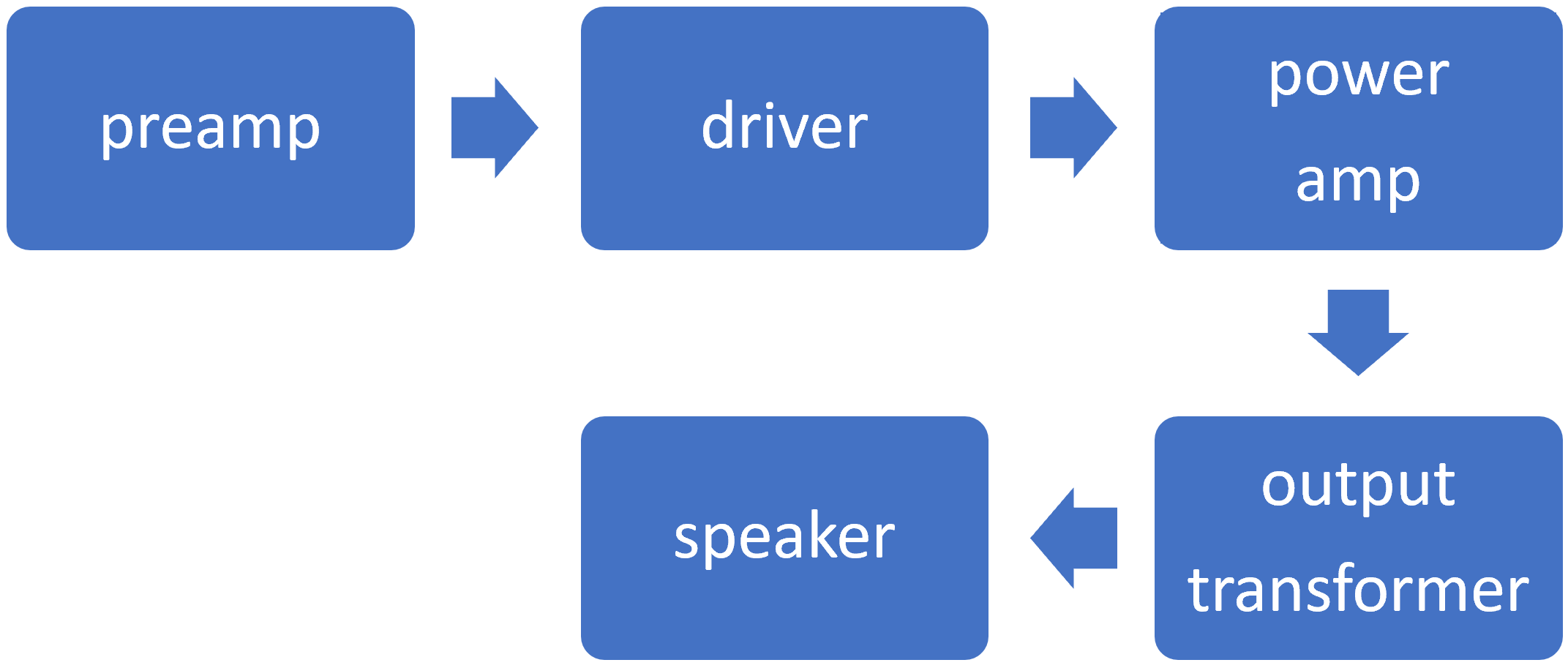
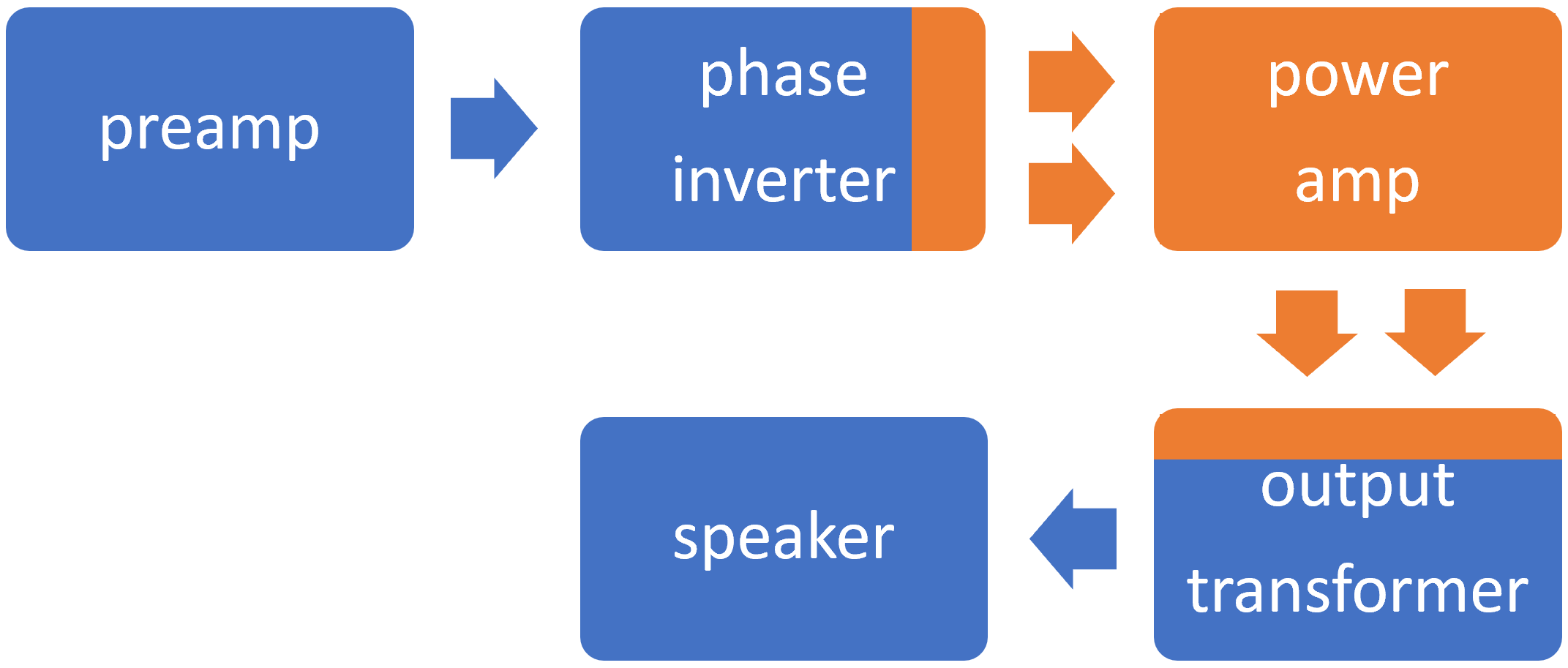
Traditional push-pull amplifiers remain unbalanced through the preamp stages but use a phase inverter to create a balanced signal to drive the power amp. Its input is the voltage difference between the power tube grids. Its output is the voltage difference between the power tube plates. The output transformer converts the balanced signal to an unbalanced signal to drive the speaker.
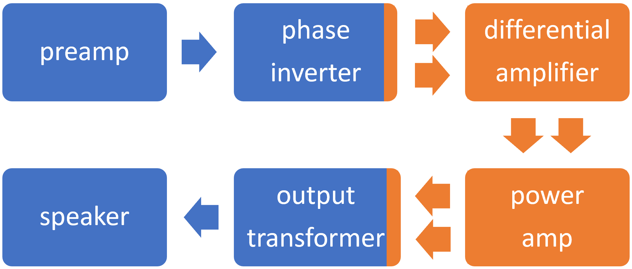
These two concepts dominate guitar amplifier system design.1 There are rare exceptions, however, such as placing an amplification stage between the phase inverter and the power amp. The Silvertone Model 1335, produced from 1954 to 1957, and the Danelectro Model 89, also produced in the mid-1950s, use a differential amplifier to amplify both phases of the balanced signal in the same circuit.
"A lot of guys have turned on to the lo-fi beauty of Danelectro and Silvertone amps over the years." 2 -Dave Hunter
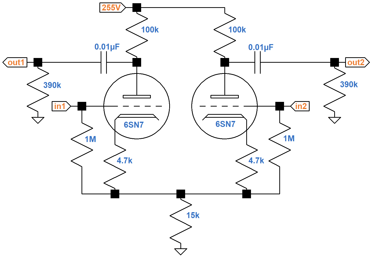
The phase inverter is a concertina, also known as a cathodyne or split-load phase inverter.3 Except for the 4.7kΩ cathode resistors, the differential amplifier looks remarkably similar to a long-tailed-pair phase inverter.

|
Guitar Amplifier Electronics: Basic Theory - master the basics of preamp, power amp, and power supply design. |
DC Operating Conditions
The 15kΩ tail resistor carries the plate current of two triodes, so the equivalent for one triode is 30kΩ.
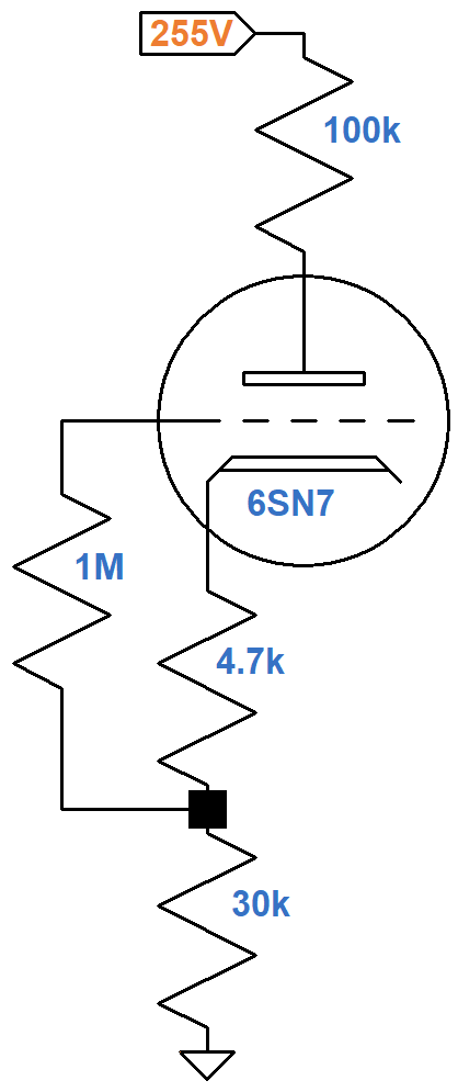
If there is no plate current, then there are no voltage drops across the resistors, so the plate-to-cathode voltage is 255V. If the plate-to-cathode voltage is 0V, then according to Ohm's Law the plate current is
255V / (100kΩ + 4.7kΩ + 30kΩ) = 1.9mA
These are the endpoints of the DC load line shown here in red.
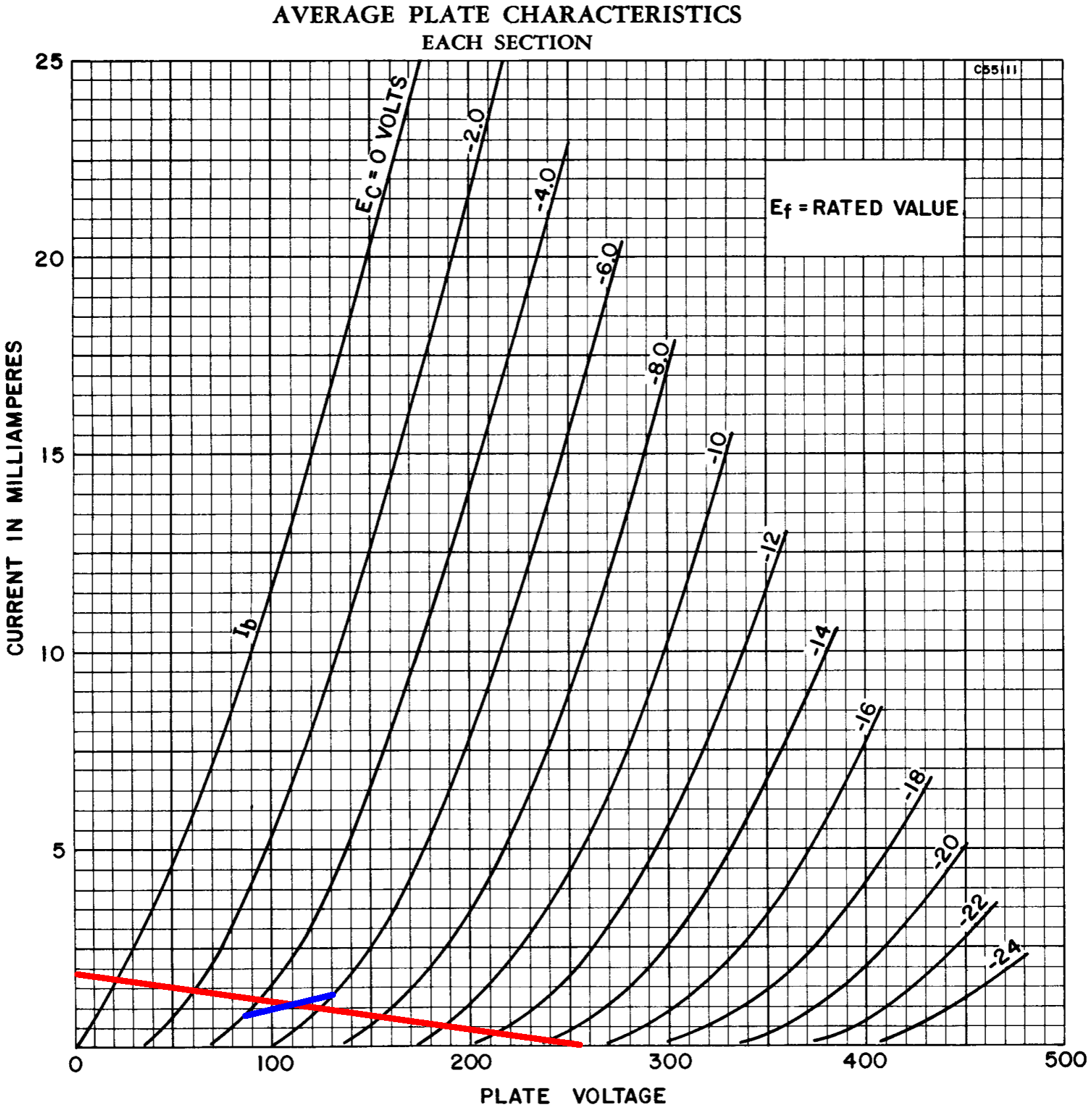
If the grid-to-cathode voltage is -4V, then according to Ohm's Law, the plate current is
4V / 4.7kΩ = 0.85mA
If the grid-to-cathode voltage is -6V, then the plate current is 1.3mA. These are the endpoints of the blue line. The two lines intersect at a DC grid bias of -5V, a plate-to-cathode voltage of 110V, and a plate current of 1.1mA, which represent the DC operating point.

|
Fundamentals of Guitar Amplifier System Design - design your amp using a structured, professional methodology. |
AC Operating Conditions
For audio signals, each 100kΩ plate load resistor is in parallel with a 390kΩ grid-leak resistor, for an equivalent resistance of 80kΩ. For the AC plate current to swing to -1.1mA, the plate voltage needs to increase by
(1.1mA)(80kΩ) = 88V
The plate voltage therefore swings from its DC value of 110V to a peak of 198V. This marks an endpoint for the green AC load line.

It indicates that plate voltage swings from 26V to 198V, which is -84V to +88V relative to the DC operating point. This is much greater than the 19V swing needed drive the power amp to full power, so the power amp is in extreme overdrive long before the upstream stage reaches its limits of headroom.

|
Guitar Amplifier Electronics: Circuit Simulation - know your design works by measuring performance at every point in the amplifier. |
AC Performance
Because the two triodes operate on opposite phases of the same signal, there is no need for a bypass capacitor across the 15kΩ tail resistor. The 4.7kΩ resistors, on the other hand, carry the current of only one phase, so for maximum gain they need to be combined to carry the current of both phases, as shown here.
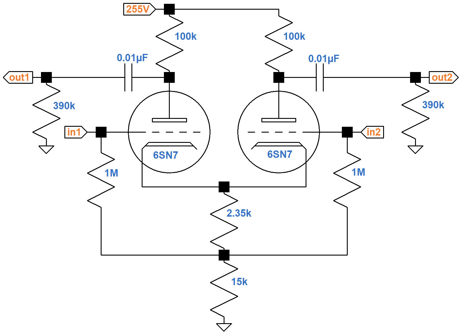
This is a long-tailed-pair phase inverter! In its most basic form, an LTP is a differential amplifier with one of its phases connected to AC ground. The 2.35kΩ resistance, representing two 4.7kΩ resistors in parallel, provides the same DC conditions. For audio, on the other hand, negative feedback due to cathode degeneration4 is removed from the circuit to maximize gain.
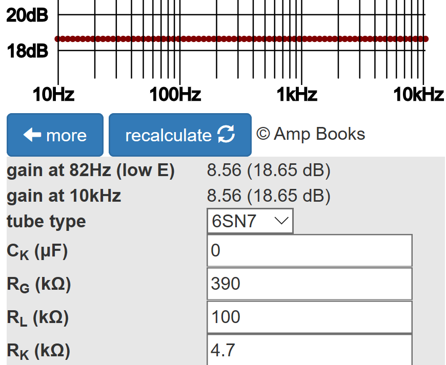
A 6SN7 has an amplification factor of 20, compared to 100 for a 12AX7. Plate resistance, on the other hand, is only 7.7kΩ, so a 6SN7 can supply more current to an AC load. Gain is the same as for a conventional voltage amplifier. According to the Cathode Bypass Capacitor calculator, the loaded gain is 25dB.
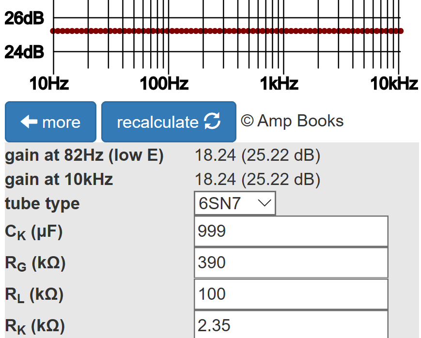
(An arbitrarily high value of 999μF is entered for the bypass capacitor to eliminate cathode degeneration.)
With the negative feedback from separate 4.7kΩ resistors, voltage gain is reduced.
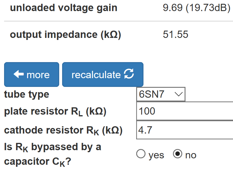
According to the Preamp Gain and Output Impedance calculator, the output impedance is 52kΩ.
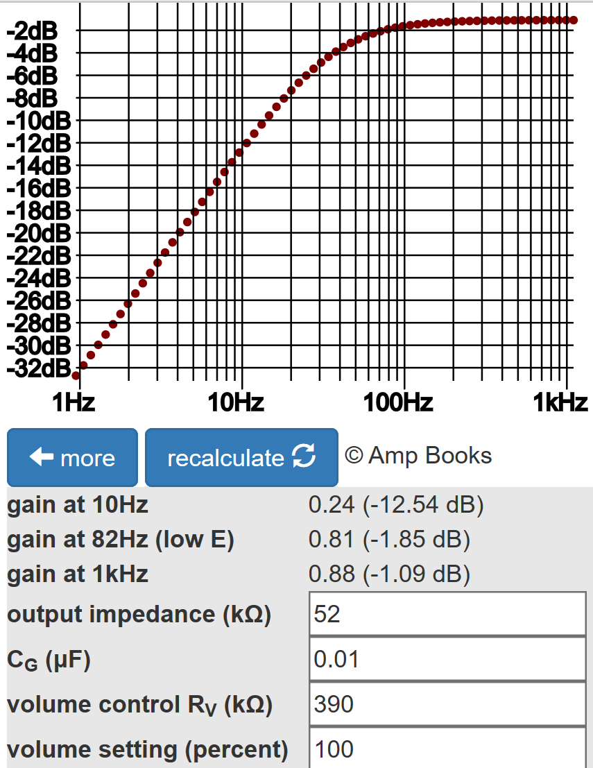
According to the Coupling Capacitor calculator, a 0.01μF value creates ample bass response.
A Balancing Act
A SPICE simulation5 confirms these results, assuming the input is perfectly balanced. Because they are identical, the red trace for one output obscures the blue trace for the other output.
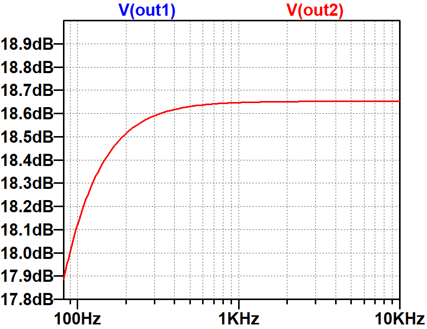
Let's rerun the simulation, but give one input a 10-percent boost: 1V peak at the first input and 1.1V peak at the second. With Danelectro's circuit, one phase of the power amp input also gets a 10-percent boost. The linear scale for the Y-axis shows that the differential amplifier helps to balances the signal. Compared to the first output, the second is only 2 percent greater.
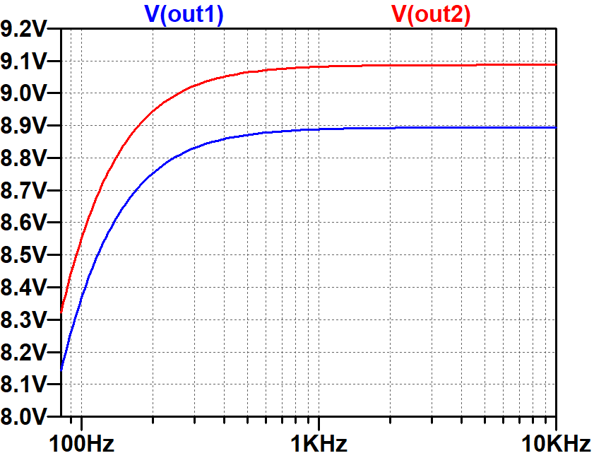
This demonstrates that a differential amplifier can improve the balance of the signals applied to the power amp. Whether this is important in the context of a harmonically-rich guitar amp is a matter of personal taste.
References
1Richard Kuehnel, Fundamentals of Guitar Amplifier System Design, (Seattle: Amp Books, 2019).
2Dave Hunter, Amped, (Minneapolis: Voyageur Press, 2012), p. 27.
3Richard Kuehnel, Guitar Amplifier Electronics: Basic Theory, (Seattle: Amp Books, 2018), pp. 130-134.
4Richard Kuehnel, Guitar Amplifier Electronics: Basic Theory, (Seattle: Amp Books, 2018), p. 61.
5Richard Kuehnel, Guitar Amplifier Electronics: Circuit Simulation, (Seattle: Amp Books, 2019).

